Quantcast
Channel: LCD Projects - PIC Microcontroller
Viewing all 253 articles
Browse latest View live

Interfacing PIC12F1822 with ST7735 SPI TFT display

$
0
0

pic12f1822+ST7735R+TFT+SPI+display+circuit

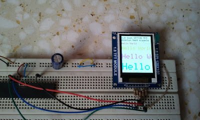
This post shows how to interface PIC12F1822 microcontroller with ST7735 SPI TFT display using CCS PIC C compiler.
For this interfacing we need a driver for the TFT display. Driver topic at the following link:
ST7735 SPI TFT Display Driver for CCS PIC C compiler
Or you can just download it directly from the following link:
ST7735 SPI TFT Display Driver
Put the downloaded C file in your project folder.
Required Components:

  • PIC12F1822 Microcontroller
  • ST7735R (or ST7735S) 1.8″ SPI TFT Display
  • 5 x 1K Resistors
  • +5V Power Supply Source
  • Breadboard
  • Jumper Wires

PIC12F1822 and ST7735 SPI TFT Example Circuit:

pic12f1822_st7735r_spi_tft_display_ccs

In this project PIC12F1822 internal oscillator is used and MCLR pin function is disabled.
PIC12F1822 and ST7735 SPI TFT Example CCS C code:
PIC12F1822 Has 1 SPI module, this module is used in this interfacing.
My TFT display is ST7735R Black Tap (ST7735S) and for initializing this type of TFT display I used the following line:
TFT_BlackTab_Initialize();
If you have a TFT display with green or red tabs or a TFT with ST7735B controller read the driver topic above.
Note that green, red and black tabs have the same controller ST7735R.
The following line enables internal oscillator @ 8MHz and also the PLL which makes the microcontroller runs at 32MHz (8MHz x 4).
setup_oscillator(OSC_8MHZ | OSC_PLL_ON);
This code is compiled with CCS PIC C compiler versions 5.051.

for more detail: PIC12F1822 and ST7735 SPI TFT Example

The post Interfacing PIC12F1822 with ST7735 SPI TFT display appeared first on PIC Microcontroller.


Interfacing PIC18F4550 with 1.8″ TFT display

$
0
0

This post shows how to connect ST7735S TFT display to PIC18F4550 microcontroller and display different things (numbers, text, lines, circles …..). The compiler used is CCS PIC C.
To interface PIC18F4550 with the ST7735 TFT display we need a small library (driver) which can be downloaded from its original post at the following url:
ST7735 SPI TFT Display Driver for CCS PIC C compiler
Or you can just download it directly from the following link:
ST7735 SPI TFT Display Driver
Put the downloaded C file in your project folder.
Required Components:

  • PIC18F4550 Microcontroller
  • ST7735R (or S) 1.8″ SPI TFT Display
  • 5 x 1K Resistors (If the system is 3.3V there is no need for these resistors)
  • Power Supply Source (+5V or +3.3V)
  • Breadboard
  • Jumper Wires

Interfacing PIC18F4550 with ST7735S 1.8″ SPI TFT display circuit:Circuit Interfacing PIC18F4550 with 1.8 TFT display

PIC18F4550 internal oscillator is used in this project and MCLR pin function is disabled.
The system power supply is 5V and if you are using a microcontroller TFT display of 3.3V remove all the 1K resistors (5 resistors) from the circuit and connect the TFT display directly to the microcontroller.
Interfacing PIC18F4550 with ST7735S 1.8″ SPI TFT display CCS C code:
PIC18F4550 SPI module is used for to communicate with the TFT display. SPI module uses the following pins:
SDI (RB0): data input pin (not used in this project)
SCK (RB1): clock line
SDO (RC7): data output
// TFT module connections
#define TFT_CS  PIN_B2
#define TFT_DC  PIN_B3
#define TFT_SPI_HARDWARE
// End TFT module connections

My TFT display is ST7735R Black Tap (ST7735S) and for initializing this type of TFT display I used the following line:Interfacing PIC18F4550 with 1.8 TFT display
TFT_BlackTab_Initialize();
If you have a TFT display with green or red tabs or a TFT with ST7735B controller read the driver topic above.
Note that green, red and black tabs have the same controller ST7735R.
The microcontroller runs with its internal oscillator at 8MHz.
This code is tested with CCS PIC C compiler PCWHD versions 4 and 5.


For more detail: Interfacing PIC18F4550 with 1.8″ TFT display

The post Interfacing PIC18F4550 with 1.8″ TFT display appeared first on PIC Microcontroller.

Multipulxing 7 Segment Display using PIC18F2550 Microcontroller

$
0
0

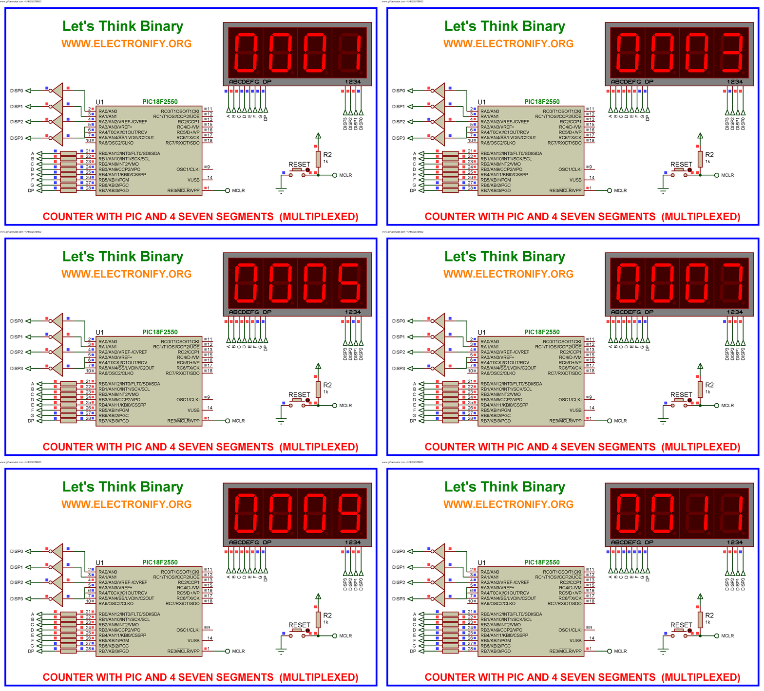
This tutorial describes how to implement decimal counter which will increment from 0000 to 9999 ; in multiplexed seven segment display using PIC18F2550 in PROTEUS ISIS.

Multiplexing is required when we want to interface 3 or 4 or even more such displays with MCU ssince it we go for normal way it will require lots of IO port.This means to turn on one at a time, extra brightly, and scan through all the digits fast enough that the eye blurs the ON and OFF.

Whatis a Seven Segment Display ?

A Seven Segment Display (SSD) is one of the most common, cheap and simple to use display. Seven Segment Displays are of two types :

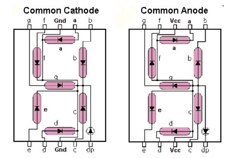
Common cathode : In the common cathode type SSD, the –ve terminal of all the LEDs are commonly connected to the ‘COM’ pin. A segment can be lighted up when ‘1’ is given to the respective LED segment and ground is connected to the common.
Common anode : In the common anode type SSD, the +ve terminal of all the LEDs are commonly connected to the ‘COM’ port of the SSD. A segment can be lighted up when the ‘COM’ port is connected to the +ve battery supply, and ground is given to the respective segment.

It looks like this :
MULTIPLEXING 7 SEGMENT DISPLAY USING PIC18F2550 MICROCONTROLLER1

For more information about seven segment https://www.electronify.org/basic-component-introduction/seven-segment-interface

Description :

All the similar segments of multiple LED displays are connected together and driven through a single I/O pin.

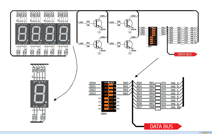
Instead, 4 NPN transistors are used as switches to connect or disconnect the cathode terminals from Gnd. When the base of the NPN transistor is high, the transistor conducts and corresponding digit’s common cathode is connected to GND. Therefore, the transistor selects which displays is active. The conduction of the transistors are controlled by RA0 through RA3 pins of PORTA. Suppose, if we want to display 7 in the units digit place, then segments a, b, and c should be turned on first (which means RB0, RB1, RB2 are 1 and RB3-RB6 are 0) and then RA0 should be pulled up (while keeping RA1-RA3 low) so that only units digit display will be active. In order to display all 4 digits, each seven-segment display is activated sequentially using an appropriate refresh frequency so that it will appear that all the them are turned on at the same time.

We have four 7-segment displays connected to the same PORTB on the PIC18F2550. Because the circuit is connected in this way we have to multiplex the output.

switch on display 1 and switch off the other 3 displays (2, 3,4)
switch on display 2 and switch off the other 3 displays (1, 3,4)
switch on display 3 and switch off the other 3 displays (1, 2,4)
switch on display 4 and switch off the other 3 displays (1, 2,3)

MULTIPLEXING 7 SEGMENT DISPLAY USING PIC18F2550 MICROCONTROLLER2

Decoding Function :

function which will return Seven Segment Decoded mask of a single digit.

Multipulxing 7 Segment Display using PIC18F2550 Microcontroller (Code)


unsignedintmask(int a)
{
switch(a)
{
case 1: return 0x06;
case 2: return 0x5B;
case 3: return 0x4F;
case 4: return 0x66;
case 5: return 0x6D;
case 6: return 0x7D;
case 7: return 0x07;
case 8: return 0x7F;
case 9: return 0x6F;
case 0: return 0x3F;
}
}

Software :

The firmware is written in C and compiled with MikroC Pro for PIC V7.1.0.

Download crack version :https://www.facebook.com/groups/816450708460518/1123157827789803/

CODE :

#include "Display_Utils.h"
unsigned short shifter, portb_index;
unsigned int digit, number;
unsigned short portb_array[4];
void interrupt() {
PORTA = 0; // Turn off all 7seg displays
PORTB = portb_array[portb_index]; // bring appropriate value to PORTD
PORTA = shifter; // turn on appropriate 7seg. display
// move shifter to next digit
shifter <<= 1; if (shifter > 8u)
shifter = 1;
// increment portd_index
portb_index++ ;
if (portb_index > 3u)
portb_index = 0; // turn on 1st, turn off 2nd 7seg.
TMR0L = 0; // reset TIMER0 value
TMR0IF_bit = 0; // Clear TMR0IF
}
void main() {
ADCON1 =0x0F; // Configure PORTX pins as digital
CMCON = 0x07; // comparators OFF
TRISA = 0; // Configure PORTA as output
PORTA = 0; // Clear PORTA
TRISB = 0; // Configure PORTD as output
PORTB = 0; // Clear PORTD
T0CON = 0xC4; // Set TMR0 in 8bit mode, assign prescaler to TMR0
TMR0L = 0; // clear TMROL
digit = 0;
portb_index = 0;
shifter = 1;
number = 9980; // Initial number value
GIE_bit = 1;
TMR0IE_bit = 1;
do {
digit = number / 1000u ; // extract thousands digit
portb_array[3] = conversion(digit); // and store it to PORTD array
digit = (number / 100u) % 10u; // extract hundreds digit
portb_array[2] = conversion(digit); // and store it to PORTD array
digit = (number / 10u) % 10u; // extract tens digit
portb_array[1] = conversion(digit); // and store it to PORTD array
digit = number % 10u; // extract ones digit
portb_array[0] = conversion(digit); // and store it to PORTD array
Delay_ms(400); // one second delay
number++ ; // increment number
if (number > 9999u)
number = 0;
} while(1); // endless loop
}

Multipulxing 7 Segment Display using PIC18F2550 Microcontroller (Schematic Diagram)

MULTIPLEXING 7 SEGMENT DISPLAY USING PIC18F2550 MICROCONTROLLER schematic diagram

Results :
After the c code is successfully compiled, a HEX file is generated.For simulating with PROTEUS ISIS hit run button and and then you will get above output.

we can drive more than one Seven Segment Display by using a technique called ‘Multiplexing’. This technique is based on the principle of Persistence of Vision of our eyes. If the frames change at a rate of 25 (or more) frames per second, human eye can’t detect that visual change. Each display is turned on above this rate and our eyes will think that the display is turned on for whole the time.

We have used Common Cathode Seven Segment Display in this example. Pins RD0 – RD6 are connected to the A – G of the display.  This will count from 0000 to 9999.

Resource :

You can download the MikroC Source Code and Proteus files etc from here download

The same application with PIC16F877A :https://drive.google.com/file/d/0B2IMfviPpUnLeWlJbHZHNnpEY1k/view

This Our Group (thanks to join and participate) : https://www.facebook.com/groups/816450708460518/

Facebook page (thanks to join and share) :

https://www.facebook.com/Lets-Think-Binary-1728910547340654/

Youtube Channel (thanks to subscribe) :

https://www.youtube.com/channel/UCTIAzxEkyeA6HTvl_VHd-Tw

The post Multipulxing 7 Segment Display using PIC18F2550 Microcontroller appeared first on PIC Microcontroller.

How to make own serial LCD display for PIC12F683 Microcontroller

$
0
0

Alphanumeric LCD generally HD44780 model is very popular display . This LCD use 8 pins for data display and three pin for control and AL together 16 pin . There will be problem on project if we have to connect numbers of components in single micro-controller to make a compact type of device . To reduce number of pin used in this tutorial we are going to make a serial LCD using data shifting technique.

In This project i am going to show you how to convert your parallel LCD display to serial LCD . Serial LCD is a little bit expensive but if we know this technique we can easily make cheap serial LCD by adding a 74HC595 chip .
code for this project is shown below

How to make own serial LCD display for PIC12F683 Microcontroller (Code)


#define _LCD_FIRST_ROW 0x80 //Move cursor to the 1st row
#define _LCD_SECOND_ROW 0xC0 //Move cursor to the 2nd row
#define _LCD_THIRD_ROW 0x94 //Move cursor to the 3rd row
#define _LCD_FOURTH_ROW 0xD4 //Move cursor to the 4th row
#define _LCD_CLEAR 0x01 //Clear display
#define _LCD_RETURN_HOME 0x02 //Return cursor to home position, returns a shifted display to
//its original position. Display data RAM is unaffected.
#define _LCD_CURSOR_OFF 0x0C //Turn off cursor
#define _LCD_UNDERLINE_ON 0x0E //Underline cursor on
#define _LCD_BLINK_CURSOR_ON 0x0F //Blink cursor on
#define _LCD_MOVE_CURSOR_LEFT 0x10 //Move cursor left without changing display data RAM
#define _LCD_MOVE_CURSOR_RIGHT 0x14 //Move cursor right without changing display data RAM
#define _LCD_TURN_ON 0x0C //Turn Lcd display on
#define _LCD_TURN_OFF 0x08 //Turn Lcd display off
#define _LCD_SHIFT_LEFT 0x18 //Shift display left without changing display data RAM
#define _LCD_SHIFT_RIGHT 0x1E //Shift display right without changing display data RAM
sbit One_Wire at GP0_bit;
sbit One_Wire_Direction at TRISIO0_bit;
char msg1[] = "www.electronify.org";
char msg2[] = "4 bit One-Wire LCD";
char msg3[] = "20x4 LCD display";
char msg4[] = "HD44780 model";
void Delay_6ms() {
Delay_ms(6);
}
void Delay_15us() {
Delay_us(10);
}
void Send_Byte(char rs, char out_char) {
char i = 0, mask = 0x80;
out_char.F1 = rs;
for(i = 0; i < 7; i++) { // send all 7 bits if(out_char & mask) { // if HI bit, make 1uS low pulse One_Wire = 0; // make LO pulse One_Wire = 1; // end LO pulse Delay_15uS(); // safe 15uS pulse recovery } else { // else is LO bit! One_Wire = 0; Delay_15uS(); // 15uS LO pulse One_Wire = 1; Delay_15uS(); // 30uS recovery Delay_15uS(); } // now we have sent that bit out using Shift1 timed protocol! mask >>= 1; // get the next bit
}
// The Shift1 protocol requires that the 8th bit is very
// long, this causes the 74HC595 shift register to latch
// all the 8 bits to its output port.
// NOTE! the 8th bit (bit0) will always be received as zero.
One_Wire = 0; // send 8th bit, lo pulse = 14x15 = 210uS
//for(i = 10; i; i--)Delay_15uS();
Delay_us(210);
One_Wire = 1; // and hi recovery 20x15 = 300 uS
//for(i = 14; i; i--)Delay_15uS();
Delay_us(300);
}
void Write_Nibbles(char rs, char out_char) {
char data2Send;
data2Send = out_char & 0xF0;
data2Send.F3 = 1;
Send_Byte(rs,data2Send);
data2Send.F3 = 0;
Send_Byte(rs,data2Send);
data2Send = out_char & 0x0F;
data2Send <<= 4; data2Send.F3 = 1; Send_Byte(rs,data2Send); data2Send.F3 = 0; Send_Byte(rs,data2Send); } void Write_Nibble(char out_char) { char data2Send, rs = 0; data2Send = out_char & 0xF0; data2Send.F3 = 1; Send_Byte(rs,data2Send); data2Send.F3 = 0; Send_Byte(rs,data2Send); } void One_Wire_LCD_Cmd(char out_char) { char rs = 0; Write_Nibbles(rs,out_char); Delay_ms(5); } void One_Wire_LCD_Chr(char row, char col, char out_char) { char rs = 1; switch(row){ case 1: One_Wire_LCD_Cmd(0x80 + col-1); break; case 2: One_Wire_LCD_Cmd(0xC0 + col-1); break; case 3: One_Wire_LCD_Cmd(0x94 + col-1); break; case 4: One_Wire_LCD_Cmd(0xD4 + col-1); break; } Write_Nibbles(rs,out_char); } void One_Wire_LCD_Chr_Cp(char out_char) { char rs = 1; Write_Nibbles(rs,out_char); } void One_Wire_LCD_Out(char row, char col, char *text) { while(*text) One_Wire_LCD_Chr(row,col++,*text++); } void One_Wire_LCD_Out_Cp(char *text) { while(*text) One_Wire_LCD_Chr_Cp(*text++); } void One_Wire_LCD_Init() { Delay_ms(150); Write_Nibble(0x30); Delay_ms(30); Write_Nibble(0x30); Delay_ms(30); Write_Nibble(0x30); Delay_ms(30); Write_Nibble(0x20); Delay_ms(20); One_Wire_LCD_Cmd(0x28); Delay_ms(10); One_Wire_LCD_Cmd(0x06); Delay_ms(10); } void main() { ANSEL = 0x00; TRISIO = 0x00; GPIO = 0x00; One_Wire = 1; One_Wire_LCD_Init(); One_Wire_LCD_Cmd(_LCD_CLEAR); One_Wire_LCD_Cmd(_LCD_CURSOR_OFF); One_Wire_LCD_Out(1,1,"One-Wire"); One_Wire_LCD_Out(2,1,"Serial LCD"); One_Wire_LCD_Out(3,1,"20x4"); One_Wire_LCD_Out(4,1,"Using 74HC595"); while(1){ } }

How to make own serial LCD display for PIC12F683 Microcontroller (Schematic Diagram)

How to make own serial LCD display for PIC12F683 microcontroller schematic diagram

How this works ?

74hc595 is a kind of shift register . This chip converts serial data to parallel data (in this project we are connecting LCD on 4 bit mode this mode also shift remaining 4 bit data to higher register bit inside the LCD ) , so we are not doing anything new , we are just converting serial data into parallel so that we can reduce number of pin used on micro-controller .The shift register holds what can be thought of as eight memory locations, each of which can be a 1 or a 0.
To set each of these values on or off, we feed in the data using the ‘Data’ and ‘Clock’ pins of the chip. The clock pin needs to receive eight pulses, at the time of each pulse, if the data pin is high, then a 1 gets pushed into the shift register, otherwise a 0. When all eight pulses have been received, then enabling the ‘Latch’ pin copies those eight values to the latch register. This is necessary, otherwise the wrong LEDs would flicker as the data was being loaded into the shift register.

How to make own serial LCD display for PIC12F683 microcontroller 2

The post How to make own serial LCD display for PIC12F683 Microcontroller appeared first on PIC Microcontroller.

PROJECT FINAL WRITE-UP

$
0
0

Our efforts in this project were to create a version of a Microchip mid-range PIC microcontroller in verilog to run on an Altera DE2 board.  It was primarily planned to create a machine that would follow a set of pre-determined instructions and perform computation, interpretation, and control of input and output ports.  In order to prove that there was actually a processor under the hood we decided to have the controller interface with (1) a human user, (2) and LCD display, and (3) control a ship from the Redhawk Duals project.  There is actually action taken on input from all three sources and control output to the LCD and Basic Ship of the duals project.  In an attempt to make writing the code for the controller as easy as possible, the architecture was made to resemble a true PIC so that a C compiler could be used to generate the software interface.

PROJECT FINAL WRITE-UP

Almost all of the instruction words would be needed to be compatible with the compiler, so after building the verilog PIC every instruction would be needed to be simulated and tested with different values to ensure that the PIC acts as expected.  The words not needed are CLRWDT to clear the unimplemented watch-dog timer, RETFIE which is used during returns from interupts which are not implemented, and SLEEP which puts the PIC in low power mode.

6bc7676fc081e939d53b9fbea05fb231

The IO ports are 8 bit bidirectional ports that are direction controlled from a TRIS port that determines whether the pins are input or out put, and can control it on a bit by bit basis, or not by requiring the designer to make all 8 bits one direction or another.  So they needed to be built bit by bit, and then grouped into groups of 8 for an 8 bit port.

For more detail:  PROJECT FINAL WRITE-UP


The post PROJECT FINAL WRITE-UP appeared first on PIC Microcontroller.

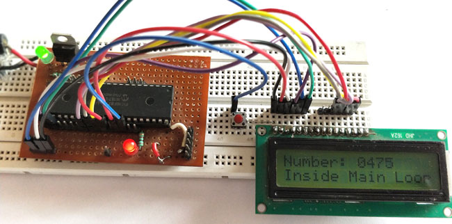
How to Use Interrupts in PIC16F877A Microcontroller

$
0
0

PIC-Interrupt-Tutorials_1

How to Use Interrupts in PIC16F877A Microcontroller

In this tutorial we will learn how to use an External Interrupt in PIC Microcontroller and why/where we will need them. This is a part of the sequence of PIC Tutorials in which we started learning PIC Microcontrollers from scratch; hence this tutorial assumes that you are familiar with how to program a PIC MCU using MPLABX and how to interface an LCD with PIC. If not please fall back to their respective links and read them trough, for I will be skipping most of the information that was already covered there.

Materials Required:

  1. PIC16F877A Perf Board
  2. 16×2 LCD Display
  3. Push Button
  4. Connecting Wires
  5. Bread Board
  6. PicKit 3

What are interrupts and where to use them:

Before getting into how to program PIC microcontroller interrupts, let us understand what an Interrupt actually is and where we would need to use them. Further, there are lots of types of interrupts in Microcontroller and PIC16F877A has about 15 of them. Let us not confuse them all into our head for now.

So! what is an interrupt in Microcontrollers?

As we all know microcontrollers are used to perform a set of pre-defined (programmed) activates which triggers the necessary outputs based on the input. But, while your Microcontroller is busy with executing one piece of code there might be an emergency situation where other piece of your code needs immediate attention. This other piece of code that needs immediate attention should be treated as an interrupt.

For example: Let us consider that you are playing your favourite game on your mobile and the controller (assumption) inside your phone is busy throwing all the graphics that is needed for you to enjoy the game. But, suddenly your girlfriend calls to your number. Now, the worst thing to happen is your mobiles controller to neglecting your girlfriends call since you are busy playing a game. To prevent this nightmare from happening we use something called interrupts.

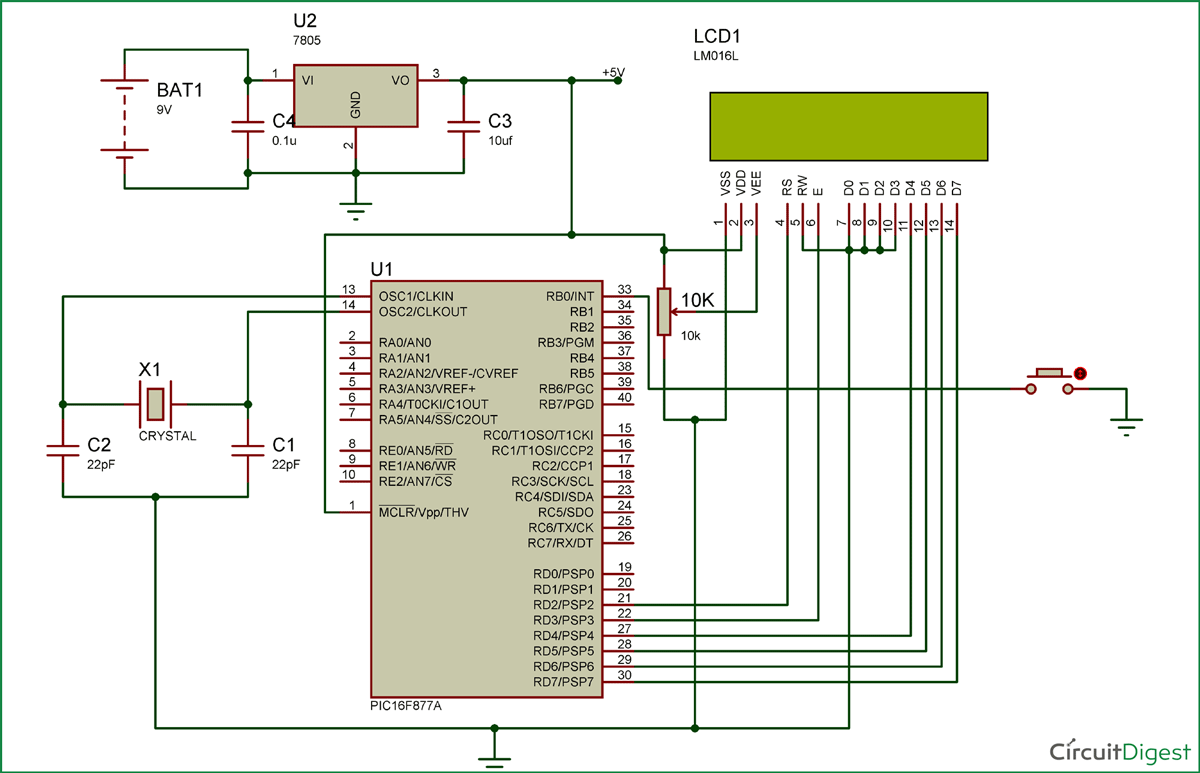
PIC16F877A-Interrupts-Circuit-Diagram

The circuit diagram for using PIC16F877 interrupts is given in the above image. You simply have to connect the LCD to the PIC as we did in interfacing LCD tutorial.

Now to connect the interrupt pin, we should look at the datasheet to know which pin of the PIC is used for External interrupt. In our case in PIC16F877A the 33rd pin RBO/INT is used for external interrupt. You cannot use any other pin other than this pin. The Pin connection for this circuit diagram is shown in the table below.

for more detail: How to Use Interrupts in PIC16F877A Microcontroller

The post How to Use Interrupts in PIC16F877A Microcontroller appeared first on PIC Microcontroller.

How to Save Data using EEPROM in PIC16F877A Microcontroller

$
0
0

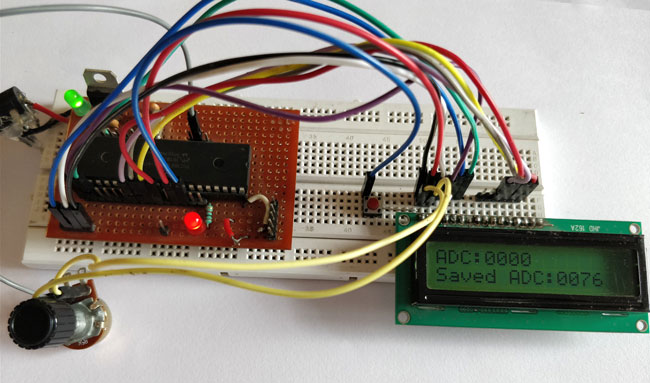
PIC-EEPROM-Project_1

Saving Data using EEPROM in PIC16F877A

In this tutorial we will learn how easy it is to save data using the EEPROM present in the PIC16F877A Microcontroller. In most real time projects we might have to save some data which should not be erased even when the power is turned off. This might sound like a complicated process, but with the help of XC8 Compiler this task can be done by just using a single line of code. If the data is large in terms of Mega bytes then we can interface a storage device like an SD card and store those data on them. But we can avoid those tiring process if the data is small, we can simply use the EEPROM present in the PIC Microcontroller to save our data and retrieve it at anytime we want

EEPROM in PIC16F877A:

EEPROM stand for “Electronically Erasable and Programmable Read Only Memory”. As the name suggests it is a memory present inside the PIC Microcontroller in which we can write/read data by programming it to do so. The data saved in this will be erased only if it is mentioned to do so in the program. The amount of storage space available in EEPROM varies upon each microcontroller; the details will be given in Datasheet as usual. In our case for PIC16F877A the available space is 256 bytes as mentioned in its specification datasheet. Now let us see how we can use these 256 bytes to read/write data by using a simple experimental setup.

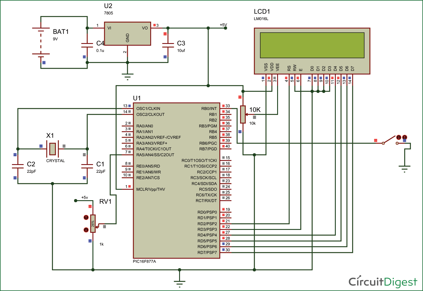
Circuit Diagram and Explanation:

PIC16F877A-EEPROM-Circuit

The circuit diagram for the project is shown above. We have interfaced an LCD to visualize the data getting saved and retrieved. A normal potentiometer is connected to AN4 Analog channel so feed in variable voltage, this variable voltage will be used as the data to be saved in the EEPROM. We have also used a push button on RB0, when this button is pressed the data from the Analog channel will be saved in the EEPROM.

for more detail:How to Save Data using EEPROM in PIC16F877A Microcontroller

The post How to Save Data using EEPROM in PIC16F877A Microcontroller appeared first on PIC Microcontroller.

Digital Speedometer and Odometer Circuit using PIC Microcontroller

$
0
0

speedometer-and-odometer-circuit-using-PIC

Digital Speedometer and Odometer Circuit using PIC Microcontroller

Measuring the speed/rpm of a Vehicle or a motor has always been a fascinating project for us to try. So, in this project we are going to build one using the Industrial ready PIC microcontrollers. We will use a piece of magnet and a Hall Sensor to measure the speed. There are other ways/sensors to measure the speed but, using a hall sensor is cheap and also can be used on any type of motor/Vehicle. By doing this project we will also enhance our skills in learning PIC16F877A since the project involves the use of Interrupts and Timers. At, the end of this project you will be able to calculate the speed and distances covered by any rotating object and display them on a 16×2 LCD screen. Lets start with this Digital Speedometer and Odometer Circuit with PIC

Simulation:

The Simulation for this project is done using Proteus. Since the project involves moving objects it is not possible to demonstrate the complete project using simulation but the working of the LCD can be verified. Simply load the hex file to the Simulation and simulate it. You will be able to notice the LCD working as shown below.

speedometer-and-odometer-circuit-using-PIC-simulation

To check of the speedometer and odometer are working I have replaced the Hall sensor with a Logic state device. During the simulation you can click on the logic state button to trigger the Interrupt and check if the speed and distance covered is getting updated as shown above.

for more detail: Digital Speedometer and Odometer Circuit using PIC Microcontroller

The post Digital Speedometer and Odometer Circuit using PIC Microcontroller appeared first on PIC Microcontroller.


Display custom characters on 16×2 lcd using Microchip Pic16f877 Microcontroller

$
0
0

Here is a simple project on how to build/generate/make custom characters in 16×2 lcd and then print/display them on lcd using microchip pic16f877 microcontroller. Character lcd contains a set of ascii characters and some Chinese characters in their controllers. We invoke the ascii characters present in the ram for displaying them on lcd. But if we want to display some special characters, symbols or similes we first have to make/declare them in the ram of lcd controller since they are not present in the ascii character set of the lcd. Then we can invoke them for displaying on the lcd when ever is required.

Building and displaying self made custom characters on lcd is not a very hard task. To carry out this task you must know about the internal structure of character lcd. The size of the lcd controller ram, registers of the lcd and CG-RAM(Character generated ram) of lcd. CG-RAM is the most important part of lcd for generating and displaying self made custom characters. CG-RAM is a whole big topic so it is kept in a separate post. CG-RAM is fully discussed in the tutorials below. I recommend you to please take the tutorials other wise you will not unable to understand the code below.

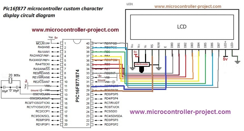
pic16f877-microcontroller-custom-character-display-circuit-diagram_orig

Pic16f877 microcontroller custom character display circuit diagram
Code is written in c language. MP-LAB ide and High TECH C compiler is used to compile the code. First i included the header file htc.h. This file must be included in every project which is going to be compiled in High Tech c compiler. Then frequency of the crystal is defined which is 20 MHz. Lcd control pins are defined next. Then some character arrays are defined. These character arrays are actually the custom characters which we are going to display on lcd. Delay function is used to give some arbitrary delay where needed. lcdcmd() function is sending commands to lcd. display() function is displaying characters on lcd. lcdint() function is initializing our lcd. In the main function I am generating and then displaying character on lcd.

To understand the code you must first know the internal structure of lcd. The tutorials links given above are very helpful for understanding the working and internal structure of CG-RAM of lcd. If you didn’t take the tutorials. I recommend you to please go through them before going through the code below.


The post Display custom characters on 16×2 lcd using Microchip Pic16f877 Microcontroller appeared first on PIC Microcontroller.

Interfacing PIC16F84 with DS3231 RTC

$
0
0

This post shows how to make a real time clock and calendar using PIC16F84 and DS3231 RTC.
The DS3231 uses I2C protocol to interface with the master device which is in this example the PIC16F84A MCU. In this project software I2C is used because the PIC16F84A MCU has no hardware I2C module.

PIC16F84A with DS3231 RTC hardware circuit

Hardware Required:

  • PIC16F84A microcontroller
  • 1602 LCD screen
  • 8MHz crystal oscillator
  • 2 x 22pF ceramic capacitor
  • 10K ohm variable resistor
  • 3 x 10K ohm resistor
  • 2 x push button
  • 5V supply source
  • Breadboard
  • Jumper wires

DS3231 board contains the following components:

  • DS3231 RTC – datasheet
  • 2 x 4.7K ohm resistors
  • 0.1uF ceramic capacitor
  • 3V coin cell battery

Interfacing PIC16F84 with DS3231 RTC circuit:

interfacing pic16f84a with ds3231 real time clock with setup buttons
In the circuit there are 2 push buttons (B1 & B2) connected to pin RA2 and pin RA3, the two push buttons are used to set the time as well as the calendar parameters (minutes, hours, date, month and year). Button B1 selects the parameter and B2 increments the selected parameter.
Interfacing PIC16F84 with DS3231 RTC C code:
The C code below was tested with CCS PIC C compiler version 5.051.
I used the function below to initialize the software I2C where pin RA0 and pin RA1 are used for SDA and SCL lines respectively (PIC16F84A is used as master device):
#use I2C(MASTER, SDA=PIN_A0, SCL=PIN_A1, FAST=100000)
The DS3231 works with BCD format only and to convert the BCD to decimal and vise versa I used the 2 functions below. Before displaying (after reading from DS3231), the data have to be converted from BCD to decimal, and before writing to the DS3231 (after editing the parameters) the data have to be converted from decimal to BCD:
int8 bcd_to_decimal(number)
int8 decimal_to_bcd(number)
Each function returns the converted value of the variable number.
void DS3231_display() : displays time and calendar data, before displaying time and calendar data are converted from BCD format to decimal format using the function bcd_to_decimal(number) .
int8 edit(x, y, parameter) : I used this function to edit time calendar parameters (minutes, hours, date, month and year). I used a variable named i to distinguish between the parameters:
i = 0, 1 : time hours and minutes respectively
i = 2, 3, 4: calendar date, month and year respectively
After the edit of time and calendar, the data have to be converted back to BCD format using the function decimal_to_bcd(number) and written to the DS3231.
void blink() : this small function works as a delay except that it is interrupted by the buttons B1 (connected to RA2) and B2 (connected to RA3). When called and without pressing any button the total time is 10 x 25ms = 250ms. With this function we can see the blinking of the selected parameter with a frequency of 2Hz. So a delay of 250ms comes after the print of the selected parameter and after that delay a 2 spaces is printed which makes the parameter disappears from the LCD and another 250ms delay comes after the print of the 2 spaces.

The post Interfacing PIC16F84 with DS3231 RTC appeared first on PIC Microcontroller.

Interfacing PIC12F1822 with ST7735 SPI TFT display

$
0
0

pic12f1822+ST7735R+TFT+SPI+display+circuit

This post shows how to interface PIC12F1822 microcontroller with ST7735 SPI TFT display using CCS PIC C compiler.
For this interfacing we need a driver for the TFT display. Driver topic at the following link:
ST7735 SPI TFT Display Driver for CCS PIC C compiler
Or you can just download it directly from the following link:
ST7735 SPI TFT Display Driver
Put the downloaded C file in your project folder.
Required Components:

  • PIC12F1822 Microcontroller
  • ST7735R (or ST7735S) 1.8″ SPI TFT Display
  • 5 x 1K Resistors
  • +5V Power Supply Source
  • Breadboard
  • Jumper Wires

PIC12F1822 and ST7735 SPI TFT Example Circuit:

pic12f1822_st7735r_spi_tft_display_ccs

In this project PIC12F1822 internal oscillator is used and MCLR pin function is disabled.
PIC12F1822 and ST7735 SPI TFT Example CCS C code:
PIC12F1822 Has 1 SPI module, this module is used in this interfacing.
My TFT display is ST7735R Black Tap (ST7735S) and for initializing this type of TFT display I used the following line:
TFT_BlackTab_Initialize();
If you have a TFT display with green or red tabs or a TFT with ST7735B controller read the driver topic above.
Note that green, red and black tabs have the same controller ST7735R.
The following line enables internal oscillator @ 8MHz and also the PLL which makes the microcontroller runs at 32MHz (8MHz x 4).
setup_oscillator(OSC_8MHZ | OSC_PLL_ON);
This code is compiled with CCS PIC C compiler versions 5.051.

for more detail: PIC12F1822 and ST7735 SPI TFT Example

The post Interfacing PIC12F1822 with ST7735 SPI TFT display appeared first on PIC Microcontroller.

Interfacing PIC18F4550 with 1.8″ TFT display

$
0
0

This post shows how to connect ST7735S TFT display to PIC18F4550 microcontroller and display different things (numbers, text, lines, circles …..). The compiler used is CCS PIC C.
To interface PIC18F4550 with the ST7735 TFT display we need a small library (driver) which can be downloaded from its original post at the following url:
ST7735 SPI TFT Display Driver for CCS PIC C compiler
Or you can just download it directly from the following link:
ST7735 SPI TFT Display Driver
Put the downloaded C file in your project folder.
Required Components:

  • PIC18F4550 Microcontroller
  • ST7735R (or S) 1.8″ SPI TFT Display
  • 5 x 1K Resistors (If the system is 3.3V there is no need for these resistors)
  • Power Supply Source (+5V or +3.3V)
  • Breadboard
  • Jumper Wires

Interfacing PIC18F4550 with ST7735S 1.8″ SPI TFT display circuit:Circuit Interfacing PIC18F4550 with 1.8 TFT display

PIC18F4550 internal oscillator is used in this project and MCLR pin function is disabled.
The system power supply is 5V and if you are using a microcontroller TFT display of 3.3V remove all the 1K resistors (5 resistors) from the circuit and connect the TFT display directly to the microcontroller.
Interfacing PIC18F4550 with ST7735S 1.8″ SPI TFT display CCS C code:
PIC18F4550 SPI module is used for to communicate with the TFT display. SPI module uses the following pins:
SDI (RB0): data input pin (not used in this project)
SCK (RB1): clock line
SDO (RC7): data output
// TFT module connections
#define TFT_CS  PIN_B2
#define TFT_DC  PIN_B3
#define TFT_SPI_HARDWARE
// End TFT module connections

My TFT display is ST7735R Black Tap (ST7735S) and for initializing this type of TFT display I used the following line:Interfacing PIC18F4550 with 1.8 TFT display
TFT_BlackTab_Initialize();
If you have a TFT display with green or red tabs or a TFT with ST7735B controller read the driver topic above.
Note that green, red and black tabs have the same controller ST7735R.
The microcontroller runs with its internal oscillator at 8MHz.
This code is tested with CCS PIC C compiler PCWHD versions 4 and 5.


For more detail: Interfacing PIC18F4550 with 1.8″ TFT display

Current Project / Post can also be found using:

  • pic elsidi proje
  • tft lcd interface with pic microcontroller

The post Interfacing PIC18F4550 with 1.8″ TFT display appeared first on PIC Microcontroller.

Multipulxing 7 Segment Display using PIC18F2550 Microcontroller

$
0
0

This tutorial describes how to implement decimal counter which will increment from 0000 to 9999 ; in multiplexed seven segment display using PIC18F2550 in PROTEUS ISIS.

Multiplexing is required when we want to interface 3 or 4 or even more such displays with MCU ssince it we go for normal way it will require lots of IO port.This means to turn on one at a time, extra brightly, and scan through all the digits fast enough that the eye blurs the ON and OFF.

Whatis a Seven Segment Display ?

A Seven Segment Display (SSD) is one of the most common, cheap and simple to use display. Seven Segment Displays are of two types :

Common cathode : In the common cathode type SSD, the –ve terminal of all the LEDs are commonly connected to the ‘COM’ pin. A segment can be lighted up when ‘1’ is given to the respective LED segment and ground is connected to the common.
Common anode : In the common anode type SSD, the +ve terminal of all the LEDs are commonly connected to the ‘COM’ port of the SSD. A segment can be lighted up when the ‘COM’ port is connected to the +ve battery supply, and ground is given to the respective segment.

It looks like this :
MULTIPLEXING 7 SEGMENT DISPLAY USING PIC18F2550 MICROCONTROLLER1

For more information about seven segment https://www.electronify.org/basic-component-introduction/seven-segment-interface

Description :

All the similar segments of multiple LED displays are connected together and driven through a single I/O pin.

Instead, 4 NPN transistors are used as switches to connect or disconnect the cathode terminals from Gnd. When the base of the NPN transistor is high, the transistor conducts and corresponding digit’s common cathode is connected to GND. Therefore, the transistor selects which displays is active. The conduction of the transistors are controlled by RA0 through RA3 pins of PORTA. Suppose, if we want to display 7 in the units digit place, then segments a, b, and c should be turned on first (which means RB0, RB1, RB2 are 1 and RB3-RB6 are 0) and then RA0 should be pulled up (while keeping RA1-RA3 low) so that only units digit display will be active. In order to display all 4 digits, each seven-segment display is activated sequentially using an appropriate refresh frequency so that it will appear that all the them are turned on at the same time.

We have four 7-segment displays connected to the same PORTB on the PIC18F2550. Because the circuit is connected in this way we have to multiplex the output.

switch on display 1 and switch off the other 3 displays (2, 3,4)
switch on display 2 and switch off the other 3 displays (1, 3,4)
switch on display 3 and switch off the other 3 displays (1, 2,4)
switch on display 4 and switch off the other 3 displays (1, 2,3)

MULTIPLEXING 7 SEGMENT DISPLAY USING PIC18F2550 MICROCONTROLLER2

Decoding Function :

function which will return Seven Segment Decoded mask of a single digit.

Multipulxing 7 Segment Display using PIC18F2550 Microcontroller (Code)


unsignedintmask(int a)
{
switch(a)
{
case 1: return 0x06;
case 2: return 0x5B;
case 3: return 0x4F;
case 4: return 0x66;
case 5: return 0x6D;
case 6: return 0x7D;
case 7: return 0x07;
case 8: return 0x7F;
case 9: return 0x6F;
case 0: return 0x3F;
}
}

Software :

The firmware is written in C and compiled with MikroC Pro for PIC V7.1.0.

Download crack version :https://www.facebook.com/groups/816450708460518/1123157827789803/

CODE :

#include "Display_Utils.h"
unsigned short shifter, portb_index;
unsigned int digit, number;
unsigned short portb_array[4];
void interrupt() {
PORTA = 0; // Turn off all 7seg displays
PORTB = portb_array[portb_index]; // bring appropriate value to PORTD
PORTA = shifter; // turn on appropriate 7seg. display
// move shifter to next digit
shifter <<= 1; if (shifter > 8u)
shifter = 1;
// increment portd_index
portb_index++ ;
if (portb_index > 3u)
portb_index = 0; // turn on 1st, turn off 2nd 7seg.
TMR0L = 0; // reset TIMER0 value
TMR0IF_bit = 0; // Clear TMR0IF
}
void main() {
ADCON1 =0x0F; // Configure PORTX pins as digital
CMCON = 0x07; // comparators OFF
TRISA = 0; // Configure PORTA as output
PORTA = 0; // Clear PORTA
TRISB = 0; // Configure PORTD as output
PORTB = 0; // Clear PORTD
T0CON = 0xC4; // Set TMR0 in 8bit mode, assign prescaler to TMR0
TMR0L = 0; // clear TMROL
digit = 0;
portb_index = 0;
shifter = 1;
number = 9980; // Initial number value
GIE_bit = 1;
TMR0IE_bit = 1;
do {
digit = number / 1000u ; // extract thousands digit
portb_array[3] = conversion(digit); // and store it to PORTD array
digit = (number / 100u) % 10u; // extract hundreds digit
portb_array[2] = conversion(digit); // and store it to PORTD array
digit = (number / 10u) % 10u; // extract tens digit
portb_array[1] = conversion(digit); // and store it to PORTD array
digit = number % 10u; // extract ones digit
portb_array[0] = conversion(digit); // and store it to PORTD array
Delay_ms(400); // one second delay
number++ ; // increment number
if (number > 9999u)
number = 0;
} while(1); // endless loop
}

Multipulxing 7 Segment Display using PIC18F2550 Microcontroller (Schematic Diagram)

MULTIPLEXING 7 SEGMENT DISPLAY USING PIC18F2550 MICROCONTROLLER schematic diagram

Results :
After the c code is successfully compiled, a HEX file is generated.For simulating with PROTEUS ISIS hit run button and and then you will get above output.

we can drive more than one Seven Segment Display by using a technique called ‘Multiplexing’. This technique is based on the principle of Persistence of Vision of our eyes. If the frames change at a rate of 25 (or more) frames per second, human eye can’t detect that visual change. Each display is turned on above this rate and our eyes will think that the display is turned on for whole the time.

We have used Common Cathode Seven Segment Display in this example. Pins RD0 – RD6 are connected to the A – G of the display.  This will count from 0000 to 9999.

Resource :

You can download the MikroC Source Code and Proteus files etc from here download

The same application with PIC16F877A :https://drive.google.com/file/d/0B2IMfviPpUnLeWlJbHZHNnpEY1k/view

This Our Group (thanks to join and participate) : https://www.facebook.com/groups/816450708460518/

Facebook page (thanks to join and share) :

https://www.facebook.com/Lets-Think-Binary-1728910547340654/

Youtube Channel (thanks to subscribe) :

https://www.youtube.com/channel/UCTIAzxEkyeA6HTvl_VHd-Tw

The post Multipulxing 7 Segment Display using PIC18F2550 Microcontroller appeared first on PIC Microcontroller.

How to make own serial LCD display for PIC12F683 Microcontroller

$
0
0

Alphanumeric LCD generally HD44780 model is very popular display . This LCD use 8 pins for data display and three pin for control and AL together 16 pin . There will be problem on project if we have to connect numbers of components in single micro-controller to make a compact type of device . To reduce number of pin used in this tutorial we are going to make a serial LCD using data shifting technique.

In This project i am going to show you how to convert your parallel LCD display to serial LCD . Serial LCD is a little bit expensive but if we know this technique we can easily make cheap serial LCD by adding a 74HC595 chip .
code for this project is shown below

How to make own serial LCD display for PIC12F683 Microcontroller (Code)


#define _LCD_FIRST_ROW 0x80 //Move cursor to the 1st row
#define _LCD_SECOND_ROW 0xC0 //Move cursor to the 2nd row
#define _LCD_THIRD_ROW 0x94 //Move cursor to the 3rd row
#define _LCD_FOURTH_ROW 0xD4 //Move cursor to the 4th row
#define _LCD_CLEAR 0x01 //Clear display
#define _LCD_RETURN_HOME 0x02 //Return cursor to home position, returns a shifted display to
//its original position. Display data RAM is unaffected.
#define _LCD_CURSOR_OFF 0x0C //Turn off cursor
#define _LCD_UNDERLINE_ON 0x0E //Underline cursor on
#define _LCD_BLINK_CURSOR_ON 0x0F //Blink cursor on
#define _LCD_MOVE_CURSOR_LEFT 0x10 //Move cursor left without changing display data RAM
#define _LCD_MOVE_CURSOR_RIGHT 0x14 //Move cursor right without changing display data RAM
#define _LCD_TURN_ON 0x0C //Turn Lcd display on
#define _LCD_TURN_OFF 0x08 //Turn Lcd display off
#define _LCD_SHIFT_LEFT 0x18 //Shift display left without changing display data RAM
#define _LCD_SHIFT_RIGHT 0x1E //Shift display right without changing display data RAM
sbit One_Wire at GP0_bit;
sbit One_Wire_Direction at TRISIO0_bit;
char msg1[] = "www.electronify.org";
char msg2[] = "4 bit One-Wire LCD";
char msg3[] = "20x4 LCD display";
char msg4[] = "HD44780 model";
void Delay_6ms() {
Delay_ms(6);
}
void Delay_15us() {
Delay_us(10);
}
void Send_Byte(char rs, char out_char) {
char i = 0, mask = 0x80;
out_char.F1 = rs;
for(i = 0; i < 7; i++) { // send all 7 bits if(out_char & mask) { // if HI bit, make 1uS low pulse One_Wire = 0; // make LO pulse One_Wire = 1; // end LO pulse Delay_15uS(); // safe 15uS pulse recovery } else { // else is LO bit! One_Wire = 0; Delay_15uS(); // 15uS LO pulse One_Wire = 1; Delay_15uS(); // 30uS recovery Delay_15uS(); } // now we have sent that bit out using Shift1 timed protocol! mask >>= 1; // get the next bit
}
// The Shift1 protocol requires that the 8th bit is very
// long, this causes the 74HC595 shift register to latch
// all the 8 bits to its output port.
// NOTE! the 8th bit (bit0) will always be received as zero.
One_Wire = 0; // send 8th bit, lo pulse = 14x15 = 210uS
//for(i = 10; i; i--)Delay_15uS();
Delay_us(210);
One_Wire = 1; // and hi recovery 20x15 = 300 uS
//for(i = 14; i; i--)Delay_15uS();
Delay_us(300);
}
void Write_Nibbles(char rs, char out_char) {
char data2Send;
data2Send = out_char & 0xF0;
data2Send.F3 = 1;
Send_Byte(rs,data2Send);
data2Send.F3 = 0;
Send_Byte(rs,data2Send);
data2Send = out_char & 0x0F;
data2Send <<= 4; data2Send.F3 = 1; Send_Byte(rs,data2Send); data2Send.F3 = 0; Send_Byte(rs,data2Send); } void Write_Nibble(char out_char) { char data2Send, rs = 0; data2Send = out_char & 0xF0; data2Send.F3 = 1; Send_Byte(rs,data2Send); data2Send.F3 = 0; Send_Byte(rs,data2Send); } void One_Wire_LCD_Cmd(char out_char) { char rs = 0; Write_Nibbles(rs,out_char); Delay_ms(5); } void One_Wire_LCD_Chr(char row, char col, char out_char) { char rs = 1; switch(row){ case 1: One_Wire_LCD_Cmd(0x80 + col-1); break; case 2: One_Wire_LCD_Cmd(0xC0 + col-1); break; case 3: One_Wire_LCD_Cmd(0x94 + col-1); break; case 4: One_Wire_LCD_Cmd(0xD4 + col-1); break; } Write_Nibbles(rs,out_char); } void One_Wire_LCD_Chr_Cp(char out_char) { char rs = 1; Write_Nibbles(rs,out_char); } void One_Wire_LCD_Out(char row, char col, char *text) { while(*text) One_Wire_LCD_Chr(row,col++,*text++); } void One_Wire_LCD_Out_Cp(char *text) { while(*text) One_Wire_LCD_Chr_Cp(*text++); } void One_Wire_LCD_Init() { Delay_ms(150); Write_Nibble(0x30); Delay_ms(30); Write_Nibble(0x30); Delay_ms(30); Write_Nibble(0x30); Delay_ms(30); Write_Nibble(0x20); Delay_ms(20); One_Wire_LCD_Cmd(0x28); Delay_ms(10); One_Wire_LCD_Cmd(0x06); Delay_ms(10); } void main() { ANSEL = 0x00; TRISIO = 0x00; GPIO = 0x00; One_Wire = 1; One_Wire_LCD_Init(); One_Wire_LCD_Cmd(_LCD_CLEAR); One_Wire_LCD_Cmd(_LCD_CURSOR_OFF); One_Wire_LCD_Out(1,1,"One-Wire"); One_Wire_LCD_Out(2,1,"Serial LCD"); One_Wire_LCD_Out(3,1,"20x4"); One_Wire_LCD_Out(4,1,"Using 74HC595"); while(1){ } }

How to make own serial LCD display for PIC12F683 Microcontroller (Schematic Diagram)

How to make own serial LCD display for PIC12F683 microcontroller schematic diagram

How this works ?

74hc595 is a kind of shift register . This chip converts serial data to parallel data (in this project we are connecting LCD on 4 bit mode this mode also shift remaining 4 bit data to higher register bit inside the LCD ) , so we are not doing anything new , we are just converting serial data into parallel so that we can reduce number of pin used on micro-controller .The shift register holds what can be thought of as eight memory locations, each of which can be a 1 or a 0.
To set each of these values on or off, we feed in the data using the ‘Data’ and ‘Clock’ pins of the chip. The clock pin needs to receive eight pulses, at the time of each pulse, if the data pin is high, then a 1 gets pushed into the shift register, otherwise a 0. When all eight pulses have been received, then enabling the ‘Latch’ pin copies those eight values to the latch register. This is necessary, otherwise the wrong LEDs would flicker as the data was being loaded into the shift register.

How to make own serial LCD display for PIC12F683 microcontroller 2

The post How to make own serial LCD display for PIC12F683 Microcontroller appeared first on PIC Microcontroller.

RC5 IR Remote Control Decoder with PIC12F1822 Microcontroller

$
0
0

This topic shows an easy and effective way for decoding IR (Infra-Red) remote controls that use Philips RC-5 communication protocol, but first we’ve to understand how the RC5 protocol works.
This Wikipedia links has good infos about the RC5 protocol.

RC5 IR Remote Control Decoder with PIC12F1822 Microcontroller
The RC-5 protocol was developed by Philips in the late 1980s as a semi-proprietary consumer IR (infrared) remote control communication protocol for consumer electronics.
The RC5 has 14 bits per 1 code transmission, the 14 bits can be divided into 4 parts:
The first 2 bits are start bits and they are always logic 1.
The third bit called toggle bit, it can be logic 1 or logic 0.
The next 5 bits are address bits, each device type has its address number for example TV address number is 0, CD player address = 20 …………
And the last 6 bits are command bits, each button has its command number.
For the same device for example TV all the remote control buttons has the same address but each button has its command.
The toggle bit changes whenever a button is pressed.
The RC5 protocol uses Manchester coding, logic 1 and logic 0 are coded as shown in the following drawing where toggle bit is 1, address = 0 and command is 2:

RC5 Protocol state machine:
I used the state machine shown below for decoding the RC5 protocol. The RC5 state machine checks the length of pulses and spaces transmitted from the remote control to go from state to another.

Where:
SP : Short Pulse (About 889µs)
LP : Long Pulse (About 1778µs)
SS: Short Space (About 889µs)
LS : Long Space (About 1778µs)
Basically there are 4 states: Mid1, Mid0, Start1 and Start0.
RC5 IR Remote Control Decoder with PIC12F1822 Microcontroller Circuit:

Components List:

  • PIC12F1822 Microcontroller
  •  1602 LCD
  • 74HC595 Shift Register (74HC164, CD4094 ….)
  • IR Receiver
  • 47µF Capacitor
  • 10K Resistor
  • 10K Variable Resistor
  • +5V Power Supply
  • Protoboard
  • Jumper Wires

To interface 1602 LCD with PIC12F1822 microcontroller we need 74HC595 shift register as what was done in this post:

RC5 IR Remote Control Decoder with PIC12F1822 Microcontroller  schematics
Interfacing PIC12F1822 microcontroller with LCD display
The IR receiver is used to receive the IR signals transmitted from the remote control and convert this signals to a digital data (logic 0 and logic 1). The microcontroller reads digital data from the IR receiver, this data is decoded and the results displayed on the 1602 LCD.

Read more: RC5 IR Remote Control Decoder with PIC12F1822 Microcontroller 

The post RC5 IR Remote Control Decoder with PIC12F1822 Microcontroller appeared first on PIC Microcontroller.

Circuit Designing of LCD with PIC

$
0
0
Hello friends, hope you all are fine and enjoying good health. Today I am posting the next part of Proteus tutorial which is Interfacing of LCD with PIC Microcontroller. . In the previous post of this tutorial, we have seen the basics of Proteus and discussed various functions of Proteus ISIS. If you are new to Proteus then I would recommend that before starting this tutorial, you should first read the first part so that you get the better idea of Proteus as I wont go in detail in today’s post. Today, we will first design a circuit of LCD with PIC on Proteus ISIS which includes PIC Microcontroller and then we will see how to burn the microcontroller in Proteus and at the end we will run our circuit and will display some text on the LCD. It will be quite a fun so let’s start.
Circuit Designing of LCD with PIC

If anyone having any problem at any point, ask in comments and I will try my best to resolve them. So, let’s get started with Interfacing of LCD with PIC Microcontroller.

Circuit Designing in Proteus

  • First of all, open the Proteus ISIS software.
  • In the start, it will look exactly the same as in below image.
  • Now click on button P as shown in below figure.

Circuit Designing in Proteus

  • When you click this button a new window will pop up as shown in below figure.
  • This is the place where we search our components, like as I want 7805 so I searched for this component and the Proteus has given me the related components.
  • Once you get your desired component, simply double click on it and it will be added in your database so that you can use them.

simply double click on it and it will be added in your database so that you can use them

  • The below image shows the components which we are gonna use in this project, so simply search for all the components and then double click on them and finally you will get all the components as shown below:

The below image shows the components which we are gonna use in this project

  • Now place these components in the Proteus workspace and connect them.
  • Design exactly the same circuit as shown in the below figure for interfacing of LCD with PIC Microcontroller.

Design exactly the same circuit as shown in the below figure for interfacing of LCD with PIC Microcontroller

  • Now our circuit in Proteus is ready to use, the next step is to write a code for the PIC Microcontroller 18F452 and then burn it into the Proteus and check its working.

    Code of LCD with PIC18F452

    • There are different compilers to write the code for PIC Microcontroller. Here I am using MikroC Pro for PIC. You can get it easily from the official site of MikroC.
    • I am not going in the details of coding as its beyond the scope of this tutorial, but still I am posting the code.
    • So now create a new project in the MikroC Pro For PIC and copy the below code and paste it in the project and compile.
    • When you compile the project, it will create a .hex file in the same folder where you have saved this project. We will use this hex file shortly.

LCD module connections
sbit LCD_RS at RD2_bit;
sbit LCD_EN at RD3_bit;
sbit LCD_D4 at RD4_bit;
sbit LCD_D5 at RD5_bit;
sbit LCD_D6 at RD6_bit;
sbit LCD_D7 at RD7_bit;

sbit LCD_RS_Direction at TRISD2_bit;
sbit LCD_EN_Direction at TRISD3_bit;
sbit LCD_D4_Direction at TRISD4_bit;
sbit LCD_D5_Direction at TRISD5_bit;
sbit LCD_D6_Direction at TRISD6_bit;
sbit LCD_D7_Direction at TRISD7_bit;
// End LCD module connections

char txt1[] = “www.TheEngineeri”;
char txt2[] = “ngProjects.com”;

char i; // Loop variable

void Move_Delay() { // Function used for text moving
Delay_ms(500); // You can change the moving speed here
}

void main(){

Lcd_Init(); // Initialize LCD
Lcd_Cmd(_LCD_CURSOR_OFF); // LCD Cursor Off
Lcd_Cmd(_LCD_CLEAR); // Clear display

Lcd_Out(1,1,txt1); // Write text in first row
Lcd_Out(2,1,txt2); // Write text in second row

Delay_ms(2000);

while(1);
}

Burn the Code in PIC Microcontroller in Proteus ISIS

  • Now we have the hex file, we need to burn this hex file in the microcontroller in Proteus.
  • So, double click on the Microcontroller in Proteus and it will open up the properties menu of PIC microcontroller.
  • Now click, as shown in the below figure, and browse for the hex file and click OK.
  • We need to add this hex file in Proteus here and also select the oscillation frequency which I have selected 16MHz.

Burn the Code in PIC Microcontroller in Proteus ISIS

Note: Make sure that the oscillation frequency remain same both in the MikroC and the Proteus.

  • After adding the file in the Proteus now click OK and play the simulation, ifeverything goes fine, you will get the results as shown in below image.

After adding the file in the Proteus now click OK and play the simulation

Note:

  • Proteus ISIS simulation file and the .hex file has been emailed to all the subscribed members. If anyone need it, subscribe to our newsletter via email and it will be emailed to you as well.

That’s all for today, I have tried my best to explain everything on Interfacing of LCD with PIC Microcontroller, but still if someone having problem ask in comments and I will try to resolve. In the next part, we will discuss various components of Proteus which are commonly used like motors, serial port, hyper terminal etc. So stay tuned and also subscribe us via email so that you get all the tutorials straight into your mail box. Have fun. Take care.

The post Circuit Designing of LCD with PIC appeared first on PIC Microcontroller.
Interfacing Graphical LCD(GLCD-JHD12864E) with Microchip PIC16f877 Microcontroller

$
0
0

In this post/tutorial i am going to teach you how to interface graphical lcd jhd12864E with microchip pic16f877 microcontroller. I am going to display my website name “www.microcontroller-project.com” and a special pattern that displays thick lines on dotted graphical lcd display. In graphical lcd name “jhd12864” the number 128×64 means lcd has 128 coulombs and 64 rows. On graphical lcd’s data(character, numbers) is displayed on dots. A joint between coulomb and row is termed as dot. Total dots present in jhd12864 lcd are 128 x 64 = 8192 dots. When dots are combined they make a dot cluster. This cluster of dots in square form is know as matrix. On these 8192 dots we can display/make our data(character, number, image). In graphical lcd’s we are free to make character’s of our desired size unless the size is in the matrix of graphical lcd.
Interfacing Graphical LCD(GLCD-JHD12864E) with Microchip PIC16f877 Microcontroller
Before proceeding i would recommend you to please go through a small tutorial. This tutorial will helps you to understand how text is displayed on graphical lcd, how graphical lcd dots are arranged in pages, how graphical lcd is initialized(Graphical Lcd initializing commands), each and every pin of graphical lcd is deeply explained in the tutorial. You can easily understand the code below if you go through the tutorial. 

​Projects Requirements

  • Microcontroller(Microchip Pic16f877)
  • Graphical Lcd(JHD12864E)
  • Crystal (20MHZ)
  • Capacitors (30pf)
  • Potentiometer-Variable resistor(0-100k)
  • Connecting Wires
  • Power Source (Battery, Adapter etc)

Graphical Lcd which i am using is JHD12864E. It comes in 20 Pin Package. Pin out of JHD12864E is given below. Its an 8-bit lcd. It comes with two built in controllers. Each controller is selected with chip select pins (cs1 and cs2). ​Visit the tutorial link given above to properly understand the pin functions and how to use them properly.

Interfacing Graphical LCD(GLCD-JHD12864E) with Microchip PIC16f877 Microcontroller schematics

Lcd data pins are connected to Port-B of pic16f877 microcontroller. Lcd is interfaced in 8-bit mode with microcontroller. RS(register select) Pin of Lcd is connected to Port-D pin#7. RW(Read/Write) Pin of Lcd is connected to Port-D Pin#6. EN(Enable) Pin of Lcd is Connected to Port-D pin#5. CS1(Chip select) Pin of Lcd is connected to Port-D pin#4. CS2(Chip select) of lcd is connected to Port-C pin#4. RST(Reset) pin of Lcd is Connected to Port-D pin#2. A variable resistor is used between pins VEE and V0. This variable resistor is very important, it sets the Lcd contrast. Just connect the resistor, vary the resistance by rotating the knob, Adjust the best quality of lcd display that suites you. You can view highly black colour dots by increasing the resistance. If you want to see fant text reduce the resistance. LED+ and LED- are back light pins. I usually switch on the back light same i did for this project.

Read more: Interfacing Graphical LCD(GLCD-JHD12864E) with Microchip PIC16f877 Microcontroller

The post Interfacing Graphical LCD(GLCD-JHD12864E) with Microchip PIC16f877 Microcontroller appeared first on PIC Microcontroller.
Display GPS Co-ordinates on LCD using pic microcontroller

$
0
0

GPS Co-ordinates on LCD: Global Positioning System. This project is about displaying GPS co-ordinates on LCD using pic microcontroller. I have already posted a project on GPS based clock using pic microcontroller. GPS is network of satellites used to send and receive accurate details about the position of anybody in the form of longitude and latitude. This process of sending and receiving positional data is done by some means of GPS modules or receiver. In our case Holux M-89 GPS module.GPS coordinates are most contains latitude and longitude. This system divides the earth into latitude lines, which indicate how far north or south of the equator a location is, and longitude lines, which indicate how far east or west of the prime meridian a location is. GPS module interfacing is done with pic microcontroller.

Display GPS Co-ordinates on LCD using pic microcontroller

Display GPS Co-ordinates on LCD using pic microcontroller

GPS Co-ordinates on LCD: Global Positioning System. This project is about displaying GPS co-ordinates on LCD using pic microcontroller. I have already posted a project on GPS based clock using pic microcontroller. GPS is network of satellites used to send and receive accurate details about the position of anybody in the form of longitude and latitude. This process of sending and receiving positional data is done by some means of GPS modules or receiver. In our case Holux M-89 GPS module.GPS coordinates are most contains latitude and longitude. This system divides the earth into latitude lines, which indicate how far north or south of the equator a location is, and longitude lines, which indicate how far east or west of the prime meridian a location is. GPS module interfacing is done with pic microcontroller.

For example the coordinates of New York Time square are 40.7589° N, 73.9851° W. The first number is used to represent latitude and second one is used to represent longitude.In this tutorial you will learn how a GPS module receives coordinates in the form of latitude and longitude from a satellite. First of all a GPS receiver   locate any three or more of satellites, calculate the distanc­e to each, and use this information to generate its own location. This operation is based on a simple mathematical principle called Trilateration.

The satellite which we used in our project is $GPGGA   has a specified purpose which is Global Positioning System Fix Data.

Some information about $GPGGA

Sentence Identifier $GPGGA Global Positioning System Fix Data
Time 170834 17:08:34 Z
Latitude 4124.8963, N 41d 24.8963′ N or 41d 24′ 54″ N
Longitude 08151.6838, W 81d 51.6838′ W or 81d 51′ 41″ W
Number of Satellites 05 5 Satellites are in view
Horizontal Dilution of Precision (HDOP) 1.5 Relative accuracy of horizontal position
Altitude 280.2, M 280.2 meters above mean sea level
Height of geoid above WGS84 ellipsoid -34.0, M -34.0 meters

Required Components:

  • PIC 16F877a: If you are an electronic hobbyist then you are familiar with microcontrollers. This MCU is easy-to-program. It is 8-bit microcontroller architecture into an 40 pins package. The PIC16F887 contains 256 bytes of EEPROM data memory, 2 Comparators, 14 channels of 10-bit Analog-to-Digital converter and much more in single chip.
  • Holux M-89 GPS module: This module is small in size, consume less power and highly efficient and user friendly. It is easy to use in ant project.
  • LCD Module: It is used to display the alpha-numeric characters. In our project it is used to display longitude and latitude.
  • Miscellaneous: Breadboard, Pickit and some jumper wires.

Display GPS Co-ordinates on LCD using pic microcontroller schematics

Use of GPS

Now a day’s GPS is use is very common. Normally it is used in follow fields:

  1. Location – such as location of a car or a aircraft.
  2. Navigation – from one location to another.
  3. Tracking – monitoring anything it may be person used by militaries.
  4. Mapping – provides maps of the world.
  5. Timing – give precise timing anywhere in the world.
  6. Security– such as monitoring a car and sending its data to server and feedback to the owner.

How it works to  navigate a car

  1. GPS receivers receive signals from satellites and detect the vehicle’s location.
  2. Direction sensor is used to detect the vehicle’s direction.
  3. Send data to server
  4. Server creates Map database.
  5. Map database is display using the car navigation system’s control circuitry.

Read more: Display GPS Co-ordinates on LCD using pic microcontroller

The post Display GPS Co-ordinates on LCD using pic microcontroller appeared first on PIC Microcontroller.

Three phase ac power measurement using pic microcontroller

$
0
0

Three phase ac power measurement: three phase watt meter using pic microcontroller is designed to measure three phase ac power of three phase transformer and three phase generator. It can be used to measure either three phase ac power of transformer or three phase generator. As you know AC power or wattage of any three phase ac equipment is difficult to measure with the help of microcontroller due to non linearity and out of phase behavior of voltage and current wave forms.  I will explain it in more detail in later part of this article.  three phase watt meters has many applications in industry. Three phase watt meters are used to measure power consumed by three phase induction machines and they are also used in power system as energy meter to measure power consumed by the user.

Three phase ac power measurement using pic microcontroller

So Now lets get start with basic components used in this project.

Component of three phase watt meter

Following are the main components used in three phase ac power measurement system using pic microcontroller.

PIC18F4550 pic microcontroller: It is the main part of this project. It is used to measure three phase ac power. It measures current, voltage and phase angle between voltage and current.  Power is calculated using product of voltage, current and power factor. It also displays value of current, voltage, ac power and frequency of each phase on LCD. you can read a article on LCD interfacing with pic16f877a microcontroller.

AC voltage measurement circuit : AC voltage measurement circuit is designed using step down transformer, full bridge rectifier and voltage divider as shown below. It also has a zero crossing detection circuit using operational amplifier. Microcontroller can not measure voltage more than 5 volt. So wee need to use a step down transformer which converts 220 volt AC into 12 volt AC. But this 12 Volt AC also has negative cycle, so we used have bridge rectifier circuit to remove negative cycle.

Because microcontroller can not read negative voltage either. After that we use a voltage divider which further step down the 12 volt ac to below 5 volt which is in acceptable range of pic microcontroller analog to digital converter. Built in analog channel pic microcontroller measured peak value of positive half cycle and this peak voltage is converter back into rms voltage using formula of peak voltage to RMS voltage conversion.

Three phase ac power measurement using pic microcontroller schematics

Current measurement circuit : Current measurement circuit also works on same principle as voltage measurement circuit except current transformer is used instead of voltage transformer as shown in circuit diagram. Current transformer is used to step down high current into low current. 100A/10A step down current transformer can be used. After current transformer, a resistor is used, voltage drop across this resistor is used to measure current with the help of built in adc of pic microcontroller. Zero crossing detector is also used with current measurement circuit.  I will explain later the need of zero crossing detector.

Read more: Three phase ac power measurement using pic microcontroller

The post Three phase ac power measurement using pic microcontroller appeared first on PIC Microcontroller.

RFID based electronic lock using pic microcontroller

$
0
0

This project is about RFID based electronic lock using pic microcontroller. RFID tags are used to open and close electronic lock.  Only those users who have authentic RFID tag will be able to open lock by using their assigned RFID tags or cards. In this RFID based electronic lock, RFID module is interfaced with pic microcontroller. RFID receiver used to receive tag number through radio frequency communication and RFID receiver sends this received number through serial communication to microcontroller. Radio Frequency Identification Lock is an electronic locking system that uses automatic locking mechanism using a mobile specific Radio wave of fixed frequency to unlock a locking mechanism. It serves both as a locking and identification system.

RFID based electronic lock project objectives

  1. Locking/ Unlocking mechanism for electronic lock through microcontroller
  2. Radio Frequency Identification utilizing programmed microcontroller
  3. Locking/ Unlocking of electronic lock using RF

Components of RFID based electronic lock

  • Isolated Circuit to Power the lock:  Isolated 5 volt power supply is used to power microcontroller and RFID module.
  • Pic Microcontroller & support devices: PIC microcontroller is used in this project to receive data from RFID receiver and relay is interfaced with pic microcontroller to drive high power electronic lock. LCD interfacing is also done to display status of of card.
  • RF ID module (transmitter & receiver)
  • Electronic lock

Block diagram of RFID based electronic lock

Block diagram of RFID module is shown below. All components of this block diagram have explained very clearly above.

Block diagram of RFID based electronic lock

RFID based electronic lock using pic microcontroller

Circuit diagram of RFID based electronic lock is shown below. As you can see, we have interface a relay with microcontoller through a transistor. Relay interfacing can also done using relay driver IC instead of transistor. Relay is used because microcontroller can not provide enough current to drive relay and electronic lock.

RFID based electronic lock using pic microcontroller

The module receives the Radio Frequency from the RFID chip and sends out the data character by character to the PIC18 uC which compares the RFID with the pre-set value burnt in the microcontroller. The subsequent module consists of an electronically controlled locking system that is configured to the output port of the microcontroller. If the scanned RF ID matches the preset RFID code, it triggers the output Port and unlocks the locking mechanism. In case the RFID does not match, no output is generated at the output port and the system stays locked.

We used a transistor and relay to amplify the signal output from our micro-controller to ensure we had enough volts and current to power our lock.Some of the technical and mechanical issues faced included the sending of junk value from the tag to the rdm module if the scanning time of the radio frequency tag was elongated. This caused the string to mismatch and as a result access was blocked by the system. One mechanical issue involved the fabrication of the lock which was out of the scope for this project and we had to buy it off the shelf which was not specifically designed for this project.The future course of work includes the use of wireless communication “to” and “fro” from this system which cannot only help communicate and send information wirelessly to android app using the web server but can also be used to raise alarm in the nearest police station in case of severe breach of security.

Code of RFID based electronic lock

After initialization of the LCD and UART, we create an rfid array that can store 3 elements in it. We assign PORTD as output, where our electronic lock is physically attached. Through an If condition, we check if UART1_Data_Ready() is high i.e. if UART is ready to send data. When it is high, we read the data and store the elements into the rfid array. Through a subsequent if condition, we check if our stored ID is in the rfid array. PORTD is momentarily set high to enable the lock and access is granted. But to ensure that it closes soon after and an intruder cannot enter, it is set to low after a short delay. For the other cards that are not stored in the array, the lock does not open and access is denied. Array is cleared at the end.

This is all about RFID based electronic lock using pic microcontroller. I have explained all the thing you need to make this project. But if you are interested in purchasing code of this project , you can contact us.

The post RFID based electronic lock using pic microcontroller appeared first on PIC Microcontroller.

Viewing all 253 articles
Browse latest View live


<script src="https://jsc.adskeeper.com/r/s/rssing.com.1596347.js" async> </script>