Quantcast
Channel: LCD Projects - PIC Microcontroller
Viewing all 253 articles
Browse latest View live

Seven Segment Display Thermometer with PIC Microcontroller

$
0
0

The seven segment display is one of the most popular numeric displays used in many microcontroller applications because it’s cheap, robust and reliable. The seven segments actually consists of 8 LED (Light Emitting Diode) and it’s come with various sizes suitable for various numeric display application such as digital clock, counter, thermometer, humidity, etc. On this project we are going to show you how to drive this type of display and this time we will use the Microchip PIC16F886 microcontroller to display the room’s temperature both in Centigrade and Fahrenheit scale.

The Seven Segments Display

Many years ago before the LCD (Liquid Crystal Display) come into the arena, the seven segments display is the main player; it’s so popular and its use in almost everything not just to display the numeric value but also a character as well, such as my old Multitech Zilog Z80 microprocessor teaching board to run the BASIC language interpreter bellow:

Seven Segment Display Thermometer with PIC Microcontroller

From the above picture you could see how complex the circuit was on those days; the circuit consists of separate IC such as 8-bit microprocessor (Zilog Z80), counter timer circuit (CTC), 4K EPROM (Erasable Programmable ROM, this ROM type can be erased only by exposing it to the UV lamp) for the firmware (the board basic I/O function and BASIC language interpreter), 2K RAM for the program and the I/O controller. Thanks to today technology this complex circuit is already put into single chip known as the microcontroller and we don’t have to use this UV lamp to erase the program anymore (you must be laugh right know, but on those days that’s the only way to do it) but what remain the same is; we still use this seven segments display, mostly for displaying the numeric value.

Displaying the seven segments is just a matter of applying the correct forward bias voltage to each of the LED’s segment in the seven segments package; for example if we want to show the digit “3” than we have to apply the forward bias voltage on each of the A, B, C, D and G LED segments. The segment pins out is vary among the types and the brands, therefore you have to find out the correct pins for each segments and the common pin as well before you can start to use it.

The Room’s Temperature Project

Our room’s temperature project is use 4 seven segments display for displaying the room’s temperature. The heart of this room’s temperature project is the 8-bit 28 pins midrange Microchip PIC16F886 microcontroller (for those with the Atmel AVR background this microcontroller is comparable to the AVR ATMega8 or ATMega88 microcontroller families). The following is the complete schematic design for this project:Schematic Seven Segment Display Thermometer with PIC Microcontroller

The designed I’ve made here not solely to show the room’s temperature with the seven segments, but it serve as the good learning tools as well, as we will explore the PIC 16F886 features such as ADC (Analog to Digital Converter), PWM (Pulse Width Modulation) and the timer counter capabilities in one shoot. Ok now lets fasten your seat belt as we will run through the design concept here.

For more detail: Seven Segment Display Thermometer with PIC Microcontroller

The post Seven Segment Display Thermometer with PIC Microcontroller appeared first on PIC Microcontroller.


Lab 4: Interfacing a character LCD using PIC16F688

$
0
0

Description

HD44780 based LCD displays are very popular among hobbyists because they are cheap and they can display characters. Besides they are very easy to interface with microcontrollers and most of the present day high-level compilers have in-built library routines for them. Today, we will see how to interface an HD44780 based character LCD to a PIC16F688 microcontroller. The interface requires 6 I/O lines of the PIC16F688 microcontroller: 4 data lines and 2 control lines. A blinking test message, “Welcome to Embedded-Lab.com”, will be displayed on the LCD screen.

character LCD

Required Theory

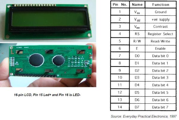
All HD44780 based character LCD displays are connected through 14 pins: 8 data pins (D0-D7), 3 control pins (RS, E, R/W), and three power lines (Vdd, Vss, Vee). Some LCDs have LED backlight feature that helps to read the data on the display during low illumination conditions. So they have two additional connections (LED+ and LED-), making altogether 16 pin. A 16-pin LCD module with its pin diagraam is shown below.

Control pins
The control pin RS determines if the data transfer between the LCD module and an external microcontroller are actual character data or command/status. When the microcontroller needs to send commands to LCD or to read the LCD status, it must be pulled low. Similarly, this must be pulled high if character data is to be sent to and from the LCD module.

The direction of data transfer is controlled by the R/W pin. If it is pulled Low, the commands or character data is written to the LCD module. And, when it is pulled high, the character data or status information from the LCD registers is read. Here, we will use one way data transfer, i.e., from microcontroller to LCD module, so the R/W pin will be grounded permanently.

The enable pin (E) initiates the actual data transfer. When writing to the LCD display, the data is transferred only on the high to low transition of the E pin.

Power supply pins
Although most of the LCD module data sheets recommend +5V d.c. supply for operation, some LCDs may work well for a wider range (3.0 to 5.5 V). The Vdd pin should be connected to the positive power supply and Vss to ground. Pin 3 is Vee, which is used to adjust the contrast of the display. In most of the cases, this pin is connected to a voltage between 0 and 2V by using a preset potentiometer.

Data pins
Pins 7 to 14 are data lines (D0-D7). Data transfer to and from the display can be achieved either in 8-bit or 4-bit mode. The 8-bit mode uses all eight data lines to transfer a byte, whereas, in a 4-bit mode, a byte is transferred as two 4-bit nibbles. In the later case, only the upper 4 data lines (D4-D7) are used. This technique is beneficial as this saves 4 input/output pins of microcontroller. We will use the 4-bit mode.

For further details on LCDs, I recommend to read these two articles first from Everyday Practical Electronics magazine : How to use intelligent LCDs Part 1, and Part 2.

Circuit Diagram

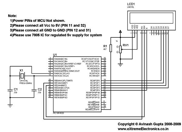
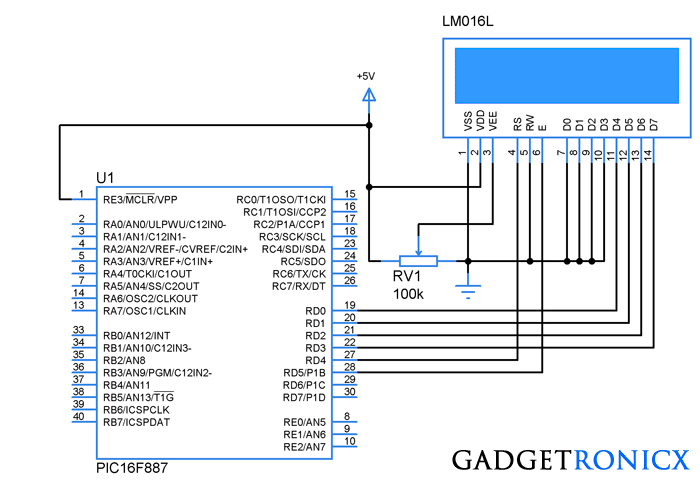
Data transfer between the MCU and the LCD module will occur in the 4-bit mode. The R/W pin (5) of the LCD module is permanently grounded as there won’t be any data read from the LCD module. RC0-RC3 serves the 4-bit data lines (D4-D7, pins 11-14) of the LCD module. Control lines, RS and E, are connected to RC4 and RC5. Thus, altogether 6 I/O pins of the PIC16F688 microcontrollers are used by the LCD module. The contrast adjustment is done with a 5K potentiometer as shown below. If your LCD module has backlight LED, use a 68Ω resistance in series with the pin 15 or 16 to limit the current through the LED. The detail of the circuit diagram is shown below.


For more detail: Lab 4: Interfacing a character LCD using PIC16F688

The post Lab 4: Interfacing a character LCD using PIC16F688 appeared first on PIC Microcontroller.

4 Bit LCD interfacing and programming with PIC Microcontroller

$
0
0

LCD displays operate in two modes 4 bit and 8 bit mode. We all might have been familiar with 8 bit mode which is used widely in several systems. But 4 bit mode is something which many of us is not aware of. This mode has some advantages over the 8 bit mode out of which reduction of dedicated data pins is most important. This tutorial will teach you 4 bit LCD interfacing in 4 bit with your controller as well as programming it.4 Bit LCD interfacing and programming with PIC Microcontroller

WHAT IS 4 BIT MODE:

We all knew that LCD consists of 8 data pins D0-D7 to receive the data and commands from the Microcontroller. However when developing a complex systems dedicating a complete port i.e 8 pins might be a drawback. To overcome this the LCD controller is capable of running in dual modes 8 bit and 4 bit mode.

8 Bit mode is a normal mode which uses 8 data lines, rs and enable for lcd functioning, see programming LCD in 8 bit mode. However in 4 bit mode only 4 lines D4-D7, along with RS,RW and EN pins are used. This will save us 4 pins of our controller which we might employ it for other purpose.

In 4 Bit mode the data bytes are sliced into two four bits and are transferred in the form of  a nibble. And the rest of the pin functions such as RS,RW and EN remains same. The above design illustrates the connection diagram of a 16×2 LCD with PIC microcontroller in 4 bit mode.

INITIALIZING THE LCD:

The first step in coding the LCD is initializing the LCD connected by giving the commands as input through the data line D4-D7 in the fom of Nibbles. For initializing the LCD following a specific reset sequence should be given and then initialized to follow the 4 bit mode.

  1. Place the byte in D4-D7 pins of LCD and set the EN pin to high and then make it low with time delay of 10ms between them.
  2. Send 28H command to use 2 lines 5×7 matrix in 4 bit mode.
  3. Send 0FH for making the LCD,cursor and Cursor blinking ON.
  4. Send 06H for incrementing cursor position.
  5. Finally 01 and 02 for clearing screen and returning home.

Schematic 4 Bit LCD interfacing and programming with PIC Microcontroller

DATA/COMMAND TRANSMISSION TO THE LCD:

The data transmission to a LCD must be performed by means of assigning logic states to three pins RS and E. R/W pin is not needed so we can ground it as shown in the schematic diagram. The data is send to the module by following these steps.

  1. RS pin should be high to convey LCD a data transmission is going to take place.
  2. Place the Upper nibble in the lower four bits of Port 2 by means of bit shifting and mask the upper four bits.
  3. Pulse En pin from high to low with certain time delay for transmission to complete.
  4. Now place the lower nibble and mask the rest of the bits, then repeat step

For more detail: 4 Bit LCD interfacing and programming with PIC Microcontroller


The post 4 Bit LCD interfacing and programming with PIC Microcontroller appeared first on PIC Microcontroller.

Transmitting and receiving data using UART protocol PIC Microcontroller

$
0
0

UART or serial communication is one of the important protocol used by the Microcontrollers to transmit and receive data from the external devices. Almost every controller is equipped with this protocol to make transmission and reception easier just using two pins. This tutorial will teach you to initialize and send data by using UART protocol PIC microcontroller.Transmitting and receiving data using UART protocol PIC Microcontroller

I assume that you are familiar with the concept of UART and proceed to explain the steps to initialize and use it in PIC controller. If you are familiar with the concept of  UART kindly go through this link before proceeding.

REGISTERS USED IN UART:

TXSTA REGISTER: This register have the status and control bits of the Transmission in the controller.

RXSTA: This register holds the status and control bits of the Reception in the microcontroller.

SPBRG: This register holds the value which decides the baud rate of the serial communication. The formula governing the calculation varies based on the modes high speed and low speed.

LOW SPEED:

(Asynchronous) Baud Rate = FOSC/(64 (X + 1))

(Synchronous) Baud Rate = FOSC/(4 (X + 1))

HIGH SPEED:

Baud Rate = FOSC/(16 (X + 1))

Where X is the value of SPBRG register.


Since we are using standard 9600 bps, we are about to use 129 in the SPBRG register. According to the datasheet it results in giving 9600 bps 20MHZ crystal. You can find brief explanation of the bits in these registers in the data sheet of this controller.Schematic Transmitting and receiving data using UART protocol PIC Microcontroller

For more detail: Transmitting and receiving data using UART protocol PIC Microcontroller

Current Project / Post can also be found using:

  • lcd displey project for pic

The post Transmitting and receiving data using UART protocol PIC Microcontroller appeared first on PIC Microcontroller.

Interfacing LCD and Keypad with PIC16F877A Microcontroller

$
0
0

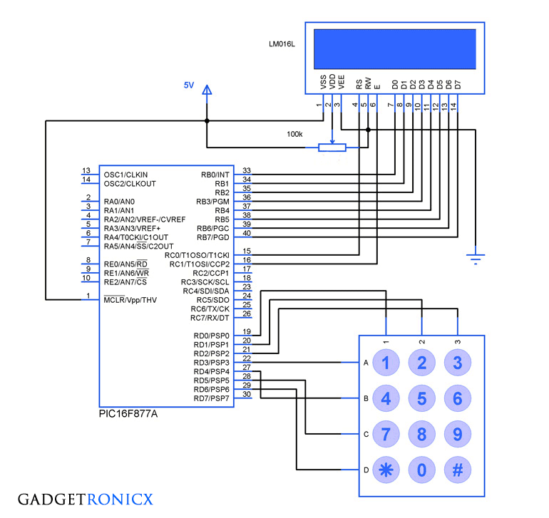
Interfacing LCD and Keypad are one of the important interfacing concepts of PIC microcontroller since both the input and output element can form a complete embedded system design. This tutorial is about teaching you how to get input input values from keypad by polling method and display the input into a 16×2 LCD.Interfacing LCD and Keypad with PIC16F877A Microcontroller

16×2 LCD:

This type of LCD is widely used to display the status of the system and to display the obtain output. This LCD consists of 16 columns and 2 rows, therefore named as 16×2 LCD. Usually a LCD consists of two built in registers known as Data and Command register. Command reg is meant for giving commands such as blink on, cursor on/off etc while Data reg is to display the input character.

You have to follow these steps to write a command or data into the LCD.

  • Place the Data/Command in the pins D0-D7 of the LCD.
  • If you are intended to write command you gotta make the RS(register select) pin of the LCD low, that is RS=0
  • Whereas for writing data you have to make this RS high, that is RS=1
  • Then the EN of the LCD must undergo a high to low logic transition with some delay in between them, that is EN=1 to EN=0 with specific delay.
  • The R/W pin should remain in the Logic 0.

Schematic Interfacing LCD and Keypad with PIC16F877A Microcontroller

4×3 Keypad:

We have used a 4×3 keypad which means it has four rows and three columns in it. The keypad was scanned for any key inputs and this was done by means of a method called polling. The scanning takes place by keeping a specific Row low at a time and read the status of the column pins as input at that instant. This chain goes on through all the rows and by this way input is read by Microcontroller.

For more detail: Interfacing LCD and Keypad with PIC16F877A Microcontroller

Current Project / Post can also be found using:

  • projects using lcd display

The post Interfacing LCD and Keypad with PIC16F877A Microcontroller appeared first on PIC Microcontroller.

How to create custom characters on 16×2 LCD using PIC18F4550

$
0
0

The 16×2 character LCD can also be used to display custom characters other than numerals, alphabets & special characters. Refer LCD interfacing with PIC. Some special shapes like hearts, arrows, smileys etc. can easily be displayed on the 5×8 pixel pattern of character LCD. These shapes are first stored at a special location in LCD’s controller and then displayed on the LCD module. This procedure has been explained here by using PIC18F4550.

The special characters are generated by bit-mapping of LCD’s 5×8 bit pixel matrix. Refer Creating custom characters on LCD using 8051 for more details on bitmap generation and storing custom values in custom generator (CG) RAM of LCD’s controller. 

16x2 LCD

The mikroC IDE provides LCD Custom Character tool to create the bitmap of user defined custom character. (Also see Working with mikroC) To create the bitmaps using this tool, following steps are to be followed:
1. Go to Tools -> LCD Custom Character
2. Select 5×7 + cursor line font and start filling the pixels in the matrix by clicking on them to create a custom character. The following figure depicts the generation of heart shape’s bitmap.
3. After creating the character and click on GENERATE button. A window will appear containing the bitmap values of designed custom character as highlighted in the following figure.
4. These bitmap values can now be used in the code.

The post How to create custom characters on 16×2 LCD using PIC18F4550 appeared first on PIC Microcontroller.

Lecture 43 : Interfacing PIC16F877 Microcontroller with an LCD

$
0
0
Aim

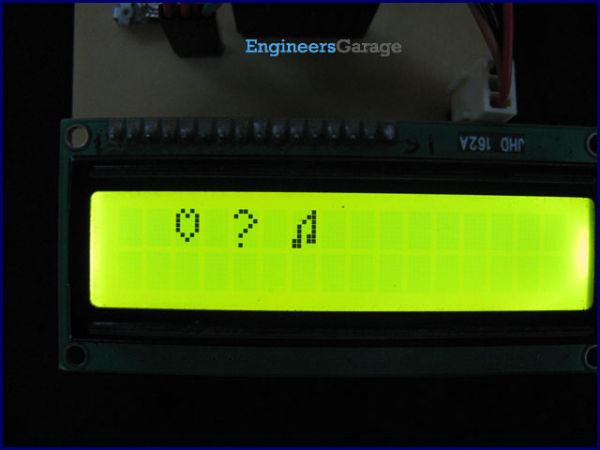
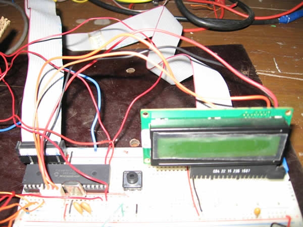
To interface LCD (Displaytech 162A) with PIC16F877microcontroller and to display “IITK” in the Liquid Crystal Display (LCD).

Components/Softwares
  1. MPLAB IDE (PIC microcontrollers simulator)
  2. PIC BURNER 3 with software to load the code
  3. LCD (Displaytech 162A)
  4. Computer System with Windows operating system and RS 232 cable
  5. PIC16F877 Microcontroller

Lecture 43  Interfacing PIC16F877 Microcontroller with an LCD

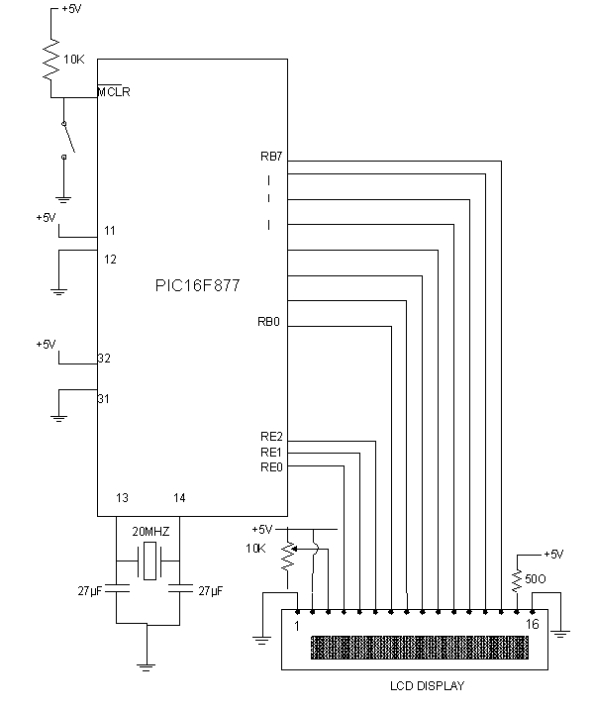
  1. +5V D.C Power Supply
  2. Resistors – 10K Ω-1,50Ω-1
  3. Capacitors – 27 µ F-2
  4. Potentiometers – 10K Ω -1
  5. 20MHz Crystal oscillator
  6. SPST switches -1
Procedure
  1. Write the assembly code in MPLAB IDE simulator , compile it and check for errors
  2. Once the code was error free, run it and check the output in the simulator.
  3. After checking the code in the simulator, load the code (in .HEX format) into PIC16F877 microcontroller using PIC BURNER3.
  4. Make connections as shown in the circuit diagram.
  5. Switch on the power supply and observe “IITK” displayed in the LCD.

Liquid Crystal Display (LCD-Displaytech 162A )LCD Displaytech 162A consists of a LCD panel, a controller IC (KS0070B) and a back light LED. The LCD module consists of total 16 pins in which, 2 are for power supply, 2 pins for Backlight LED, one pin for contrast adjustment, 3 pins are for control signals and 8 pins are data pins. In order to display any data, we need to do certain initiations. The following are the main three steps in displaying any data in the LCD display.

Lecture 43  Interfacing PIC16F877 Microcontroller with an LCD Schematic

  1. Initializing LCD by sequence of instructions
  2. Executing commands depending on our settings in the LCD
  3. Writing data into the DRAM locations of LCD in the Standard Character Pattern of LCD

For doing above steps, refer the manual for LCD and follow the instructions and timing diagrams strictly.
MPLABIDEMPLABIDE is a free software which can be downloaded from the website www.microchip.com
Working with MPLABIDE :
MPLABIDE is a simulator for PIC microcontrollers to write and edit the code in assembly language, compile it and also to run the code. Output can be verified using simulator.


For more detail: Lecture 43  Interfacing PIC16F877 Microcontroller with an LCD

The post Lecture 43 : Interfacing PIC16F877 Microcontroller with an LCD appeared first on PIC Microcontroller.

Making “The LCD Expansion Board” for PIC18F4520 using pic microcontoller

$
0
0

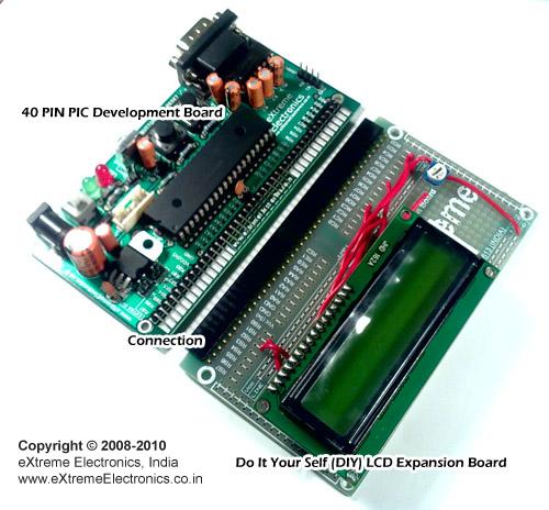
In this tutorial I you show you how to make a very useful expansion board for our PIC development board. It will be a Do It Your self (DIY) LCD Expansion board. The expansion board can be plugged into the PIC development board to add 16×2 Alphanumeric LCD Support to it. Since LCDs are required in many projects and experiments it will be a very helpful board.

 Making “The LCD Expansion Board” for PIC18F4520I recommend you to read the LCD Interfacing Tutorial before you proceed. It will give you an Idea how LCD is connected to PIC Microcontrollers. So lets start!

Fig.: LCD Module Interface with PIC Microcontroller.

The board is very easy to make as the MCU core unit is already done for you. So you need to just care about the LCD part. It consists of the 16×2 LCD Module and A variable resistor (10K) only! Optionally you can add a 47ohm series resistor with the LED backlight of the LCD Module, to enable the backlight. The variable resistor is used to adjust the contrast of the module. If NO text is displayed adjust this pot.

All I/O ports and power supply is available at the top of expansion board.

 Making “The LCD Expansion Board” for PIC18F4520

Fig.: A blank expansion.

As you can see the top row in the board lists all I/O port of PIC MCU like, RB7, RA1 etc. For Example, RB7 stands for Port B 7th bit. The row also has regulated 5v supply and GND outputs. So we start by soldering a 40 PIN Right Angled Burg Housing on the Expansion Board. This will help connect it with the PIC development board .

For more detail: Making “The LCD Expansion Board” for PIC18F4520

The post Making “The LCD Expansion Board” for PIC18F4520 using pic microcontoller appeared first on PIC Microcontroller.


Easy Debugging Terminal using PIC16F84

$
0
0

Introduction

This LCD terminal provide two modes of operation by selecting jumper J1. When J1 is open the terminal operate as a normal ascii display terminal, when J1 is closed the terminal displays the input serial data in hexadecimal format. This mode is useful for viewing raw data from the serial port output.

Hardware

Figure 1 shows the circuit diagram of the Easy Debugging Terminal. IC U2 a PIC16F84 micro controller is used to control the operation of the terminal. Input signal is applied to connector K1. The circuit can be powered either by 9V dc adapter or by using a 9V battery. Jumper J1 select the operating mode of the terminal, J1 open for ascii terminal mode, closed for hexdecimal display mode. LED D3 can be controlled by software command provided in ascii mode. This LED output can also be used (with buffer circuit) to control the backlight of the LED backlit display. Variable P1 is used to adjust the contrast of the display. The circuit uses a 16×2 line LCD module, while a 16×1 module can also be used.

Constructing the Circuit

Debugging Terminal

The prototype board may be built using universal PCB having the same size as of LCD module so that LCD module can be mounted on top of universal PCB using SIP connectors.
For the parts list of the circuit view the file Lcdbom.txt


For more detail: Easy Debugging Terminal using PIC16F84

The post Easy Debugging Terminal using PIC16F84 appeared first on PIC Microcontroller.

d.i.y. Handheld Multichannel Analyzer (MCA) based on 16F877 PIC Microcontroller and LCD

$
0
0

Some time ago I was developing a medical instrument which required histogramming, which got me in the mood to retake my own PIC MCA project(http://home.comcast.net/~prutchi/index_files/scint.htm ).

d.i.y. Handheld Multichannel Analyzer (MCA) based on 16F877 PIC Microcontroller and LCD

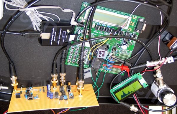
I used the variable RAM in the microcontroller (16F877), so I limited the number of channels to 95 and let the histogram run until some channel reaches 240 counts (the highest 8-bit number that yields an integer when divided by 8 which is also divisible by the 30 pixel height of the LCD).

d.i.y. Handheld Multichannel Analyzer (MCA) based on 16F877 PIC Microcontroller and LCD

The firmware then displays the spectrum as a bar with a maximum height of 30 pixels for each one of the 95 channels.

Click here for complete how-to construction instructions in pdf format.

Click here for a pdf of the schematic diagram for the front-end of the MCA


For more detail: d.i.y. Handheld Multichannel Analyzer (MCA) based on 16F877 PIC Microcontroller and LCD

The post d.i.y. Handheld Multichannel Analyzer (MCA) based on 16F877 PIC Microcontroller and LCD appeared first on PIC Microcontroller.

PIC16F877A (with LCD) not working

$
0
0

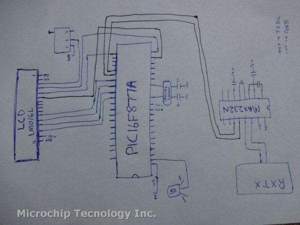
I have designed a PIC18F877A micro controller project to read temperature from an LM35 using ADC, display it on an LCD and transmit it to a serial port.

When the program starts, sometimes it shows a startup message – sometimes it doesn’t display anything.

PIC16F877A (with LCD) not workingAlso, the serial port connection is not working. Can anyone help – am I missing something? Are there any ground connections missing?
My code:
#include
#device adc=10
#fuses HS,NOWDT,NOPROTECT,NOLVP
#use delay(clock=20000000)
#use rs232 (baud=9600,rcv=PIN_C7, xmit=PIN_C6)
#include
float value;
float temp;
float temp2;
float temp3;
float temp4;
float temp5[14];
float count[14];
int c;
void main(void)

PIC16F877A (with LCD) not working schematic{//setup_adc_ports( ALL_ANALOG );//Initialize and Configure ADC
//setup_adc(ADC_CLOCK_INTERNAL );
while(1)
{
lcd_init();
lcd_gotoxy (1,1);
delay_ms(1000);
printf(lcd_putc,” WELCOME TO\n Micro Tech Sol.”);
delay_ms(3000);
lcd_gotoxy (1,1);
printf(lcd_putc,” Fuel Monitoring \n PROJECT “);
delay_ms(3000);}}


For more detail: PIC16F877A (with LCD) not working

Current Project / Post can also be found using:

  • pic based light and temperature monitoring system

The post PIC16F877A (with LCD) not working appeared first on PIC Microcontroller.

How to display text on 16×2 LCD using PIC18F4550 Microcontroller

$
0
0

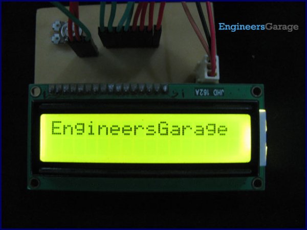
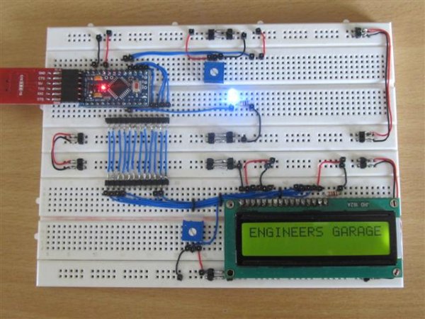
Several automated and semi-automated devices require a message to be displayed in order to indicate their working status. In continuation to LCD interfacing with PIC18F4550, this article explains how to display a message or string on a 16×2 character LCD.

How to display text on 16x2 LCD using PIC18F4550 MicrocontrollerProgramming steps:

·         Configure the LCD.
·         Store a string in a character array.
unsigned char data[20]=“EngineersGarage”;
·         Run a loop till the loop counter encounters the null character ‘\0’ of the string.
·         Use lcddata() function to send individual character values of the string to be displayed on LCD.

Code:

while(data[i]!=’\0′)
{        lcddata(data[i]);
i++;        Delay_ms(300);    }

// Program to display text on 16x2 LCD using PIC18F4550 Microcontroller

// Configuration bits
/* _CPUDIV_OSC1_PLL2_1L,  // Divide clock by 2
   _FOSC_HS_1H,           // Select High Speed (HS) oscillator
   _WDT_OFF_2H,           // Watchdog Timer off
   MCLRE_ON_3H            // Master Clear on
*/

//LCD Control pins
#define rs LATA.F0
#define rw LATA.F1
#define en LATA.F2

//LCD Data pins
#define lcdport LATB

void lcd_ini();
void lcdcmd(unsigned char);
void lcddata(unsigned char);
unsigned char data[20]="EngineersGarage";
unsigned int i=0;
How to display text on 16x2 LCD using PIC18F4550 Microcontrollervoid main(void)
{
	TRISA=0;		// Configure Port A as output port
	LATA=0;
	TRISB=0;		// Configure Port B as output port
	LATB=0;
	lcd_ini();		// LCD initialization
	while(data[i]!='\0')
	{		lcddata(data[i]);	// Call lcddata function to send characters
					// one by one from "data" array
		i++;		Delay_ms(300);
	}}void lcd_ini()
{	lcdcmd(0x38);		// Configure the LCD in 8-bit mode, 2 line and 5x7 font
	lcdcmd(0x0C);		// Display On and Cursor Off
	lcdcmd(0x01);		// Clear display screen
	lcdcmd(0x06);		// Increment cursor
	lcdcmd(0x80);		// Set cursor position to 1st line, 1st column}

void lcdcmd(unsigned char cmdout)
{	lcdport=cmdout;		//Send command to lcdport=PORTB
	rs=0;						
	rw=0;
	en=1;
	Delay_ms(10);
	en=0;


For more detail: How to display text on 16×2 LCD using PIC18F4550 Microcontroller

The post How to display text on 16×2 LCD using PIC18F4550 Microcontroller appeared first on PIC Microcontroller.

PIC Microcontroller project – 24 hour clock and thermometer displayed via 16f690 microcontroller and LCD programmed in C

$
0
0

I got to thinking that an interest in hi-fi can be a bit geek ( in a good way ) so I thought one of my latest geek projects might be of interest to some of you. You could build the project ‘as is’ without learning embedded C programming or you could use the project as a spring board to extra geekiness and weekend fun – I’ll leave that to you

Learning embedded C can be hugely rewarding and creative. The tool chain needed to get you started is either free (MPXLAB  IDE  and XC8 C compiler are both free downloads from the Microchip website and the pickit 3 needed to download compiled C code to your target microcontroller (16f690 in this case) is less than 50GBP.

PIC Microcontroller project – 24 hour clock and thermometer displayed via 16f690 microcontroller and LCD programmed in CYou might be wondering why this project might be interesting to hi-fi enthusiasts. Well I have a few suggestions … the finished project will allow you to keep tabs on the temperature of your listening room via an LM35 temperature sensor, which is important not just for your own comfort, but electro-mechanical devices such as turntables, phono cartridges and loudspeakers or headphones perform best at temperatures that are comfortable to humans like you and me – 18 Celcius to 23 Celcius for example.

The other feature, the 24 hour clock is simply a clock as implemented at the moment, which is always useful in a gadget, but with additional software development could be used to time the hours of phono cartridge use, or if you have a valve amplifier the hours of valve usage. Either way it’s a great feature as it is and leaves further firmware development up to your imagination.

Here is a roughly drawn but accurate schematic circuit diagram and also the full C source code plus full build details – if you have any questions or queries please ask! Have fun…

Here’s a top view showing the sandwich construction of the thermo_timer – the front is a layer of 4mm clear acrylic, then brass pillars stand this off from the strip board circuit board. Another set of brass pillars then stand off the second layer of 4mm clear acrylic.

Here is the rear of the prototype which shows how simple the circuit really is – just a Microchip PIC 16f690, an LM35 temperature sensor which generates 10mV/ degree Centigrade, a contrast potentiometer for the LCD, and two push buttons to set hours and minutes of the clock.

And here is the C source code for the clock thermometer project, which has been complied with the free Microchip XC8 C complier and downloaded to the 16f690 with Microchip MPLABX IDE. Feel free to copy and use/ enhance this code to learn more about the C language and the PIC range of Microcontrollers, as I did and am still doing :-) I’d be really pleased if you would link to this page if you find it helpful.

/*
// File:   lcd_thermo_clock_16f690.c
* Author: Phil Glazzard
* version 1.03 – firmware modified 1 June 2015
* Created on 26 April 2015, 14:05 – MODIFIED TRM1 PRE-LOAD TO SLOW CLOCK 11/06/2015
*/
//0XDB CHANGED TO 0XA4 IN TMR1L

// PIC16F690 Configuration Bit Settings

// ‘C’ source line config statements

#include <xc.h>

// #pragma config statements should precede project file includes.
// Use project enums instead of #define for ON and OFF.

// CONFIG
#pragma config FOSC = INTRCIO   // Oscillator Selection bits (INTOSCIO oscillator: I/O function on RA4/OSC2/CLKOUT pin, I/O function on RA5/OSC1/CLKIN)
#pragma config WDTE = OFF       // Watchdog Timer Enable bit (WDT disabled and can be enabled by SWDTEN bit of the WDTCON register)
#pragma config PWRTE = OFF      // Power-up Timer Enable bit (PWRT disabled)
#pragma config MCLRE = OFF       // MCLR Pin Function Select bit (MCLR pin function is MCLR)
#pragma config CP = OFF         // Code Protection bit (Program memory code protection is disabled)
#pragma config CPD = OFF        // Data Code Protection bit (Data memory code protection is disabled)
#pragma config BOREN = OFF      // Brown-out Reset Selection bits (BOR disabled)
#pragma config IESO = OFF       // Internal External Switchover bit (Internal External Switchover mode is disabled)
#pragma config FCMEN = OFF      // Fail-Safe Clock Monitor Enabled bit (Fail-Safe Clock Monitor is disabled)
#define _XTAL_FREQ 4000000      // 4MHz clock defined for __delay_ms() function
#define RS PORTBbits.RB7        // RS = RB7
#define E PORTBbits.RB5         // E = RB5

int thous, huns, tens, units;   // define global variables
int temp, temp1;
char tick,seconds_lsb,seconds_msb, seconds, minutes,minute_msb, minute_lsb, minutes_msb, hundreds_lsb, hundreds_msb, hours = 0;
void config_timer1(void)
{
TMR1IF = 0;                 //clear timer1 interrupt flag
TMR1L = 0;                  // clear low byte of 16 bit timer1
TMR1H = 0;                  // clear high byte of 16 bit timer1
T1CONbits.T1CKPS0 = 1;      // select 1:8 pre-scaler
T1CONbits.T1CKPS1 = 1;
PIE1bits.TMR1IE = 1;        //enable timer1 interrupt
INTCONbits.PEIE = 1;        //enable peripheral interrupt enable
INTCONbits.GIE = 1;         // enable global interrupt enable
}
void timer1_on(void)
{
TMR1H = 0x0B;               // pre-load 16 bit timer1 with 0x0BA4
TMR1L = 0xA4;               // 0.5 sec/ 2Hz frequency before overflow
T1CONbits.TMR1ON = 1;       // start timer1
}
int interrupt isr (int)
{

if (TMR1IF == 1)                   // check to see if the interrupt was caused by TMR1 overflowing
{
TMR1ON = 0;                           // turn TMR1 off
seconds = seconds + 1;                // increment seconds variable
TMR1H = 0x0B;               // pre-load 16 bit timer1 with 0x0BA4
TMR1L = 0xA4;               // 0.5 sec/ 2Hz frequency before overflow
T1CONbits.TMR1ON = 1;       // start timer
TMR1IF = 0;                 // clear TMR1 interrupt flag
RA4 = seconds;              // flip RA4 each second to flash LED at 1 Hz

temp1 = ADRESL;              //store low byte of ADC conversion in temp1
temp1 =  temp1 + (ADRESH <<8);//shift high byte of ADC conversion 8 bits left
//and add to temp1 to give 10 bit ADC result.
temp = (int)(temp1 /0.2046);//cast expression as an integer to avoid floating
//point arithmetic.
// 102.3 = 5V (Vref)so 10mV = 1deg C = 102.3/500 = 0.2046
ADIF = 0;                    // clear the ADC interrupt flag ready for next conversion
}
}

void clock()
{
E = 1;                                  // creates a 1ms pulse to clock commands and data
__delay_ms(1);                          // into the LCD module
E = 0;
}

void lcd_initialisation()
{
__delay_ms(100);                // 100ms delay after ‘power on’
RS = 0;
PORTC = 0x30;                   //Function set RS RW D7 D6 D5 D4 D3 D2 D1 D0
__delay_ms(5);                 //               0 0  0  0  1  1  0  0  0  0 = 0x30
clock();
RS = 0;
PORTC = 0x30;                      //Function set RS RW D7 D6 D5 D4 D3 D2 D1 D0
__delay_us(100);                 //               0 0 0  0  1  1  0  0  0  0 = 0x30
clock();
RS = 0;

PIC Microcontroller project – 24 hour clock and thermometer displayed via 16f690 microcontroller and LCD programmed in C SchematicPORTC = 0x30;                     //Function set RS RW D7 D6 D5 D4 D3 D2 D1 D0
__delay_us(100);                 //               0 0  0  0  1  1  0  0  0  0 = 0x30
clock();
RS = 0;
PORTC = 0x38;                   //Function set RS RW D7 D6 D5 D4 D3 D2 D1 D0
clock();                        //              0 0  0  0  1  1  1  0  0  0 = 0x38
__delay_us(200);
RS = 0;
PORTC = 0x08;                   //Display off
clock();
__delay_ms(1);
RS = 0;
PORTC = 0x01;                   // clear display
clock();
__delay_ms(10);
RS = 0;
PORTC = 0x06;                   // entry mode set
clock();
__delay_ms(1);
RS = 0;
PORTC = 0x0C;                   // LCD display ON, cursor off, cursor blinking off
clock();
__delay_ms(1);}
void clear_lcd()
{RS=0;
PORTC = 0x0F;
clock();
__delay_ms(1);}

void config_ports(void)

{


For more detail: PIC Microcontroller project – 24 hour clock and thermometer displayed via 16f690 microcontroller and LCD programmed in C

The post PIC Microcontroller project – 24 hour clock and thermometer displayed via 16f690 microcontroller and LCD programmed in C appeared first on PIC Microcontroller.

Microcontroller based Data Logger

$
0
0

Description:

This project is a fine combination of analog and digital electronics. This project is designed so as to fulfill the requirements of the industry applications, home applications. The project consists of parameters monitoring, parameter storage. PC interface is one of the main features of the project in which various data like value of parameters, date and time are sent to the PC using a hyper terminal.

We have used Microcontroller as a main component of the project. Now a Microcontroller has become a main component of many of the electronic circuits. Also Liquid Crystal Display (LCD) and EEPROM is used on major basis for the display and storage purpose. This project which will consist of two basis modules. First is “Data Monitoring” & other is “Data Storage”

Microcontroller based Data LoggerA display unit will show the value of parameters. This will help for the person to know the values, for this purpose we are going to use various sensors, which will be connected to ADC.

The other module is named as parameter storage. It can be used to store the parameter values in the memory. We are going to use EEPROM memory IC. These values can later seen using a keypad provided on the front panel. This system is useful as many times its difficult to measure the parameter values manually and also this module is more accurate than the domestic system.

Description in detail:

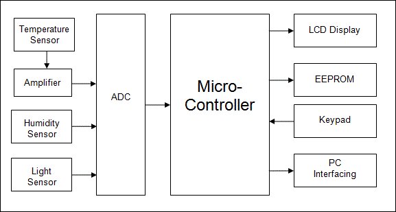
Explanation of Block Diagram:

1) SENSOR ONE: This is first sensor which uses to sense parameter one. This can be temperature sensor, say LM35. The sensor will be placed on the front panel. One can use LCD display to read the temperature.

2) SENSOR TWO: This is second sensor which uses to sense parameter two. This can be Humidity sensor, say LDR. The sensor will be placed on the front panel.

3) AMPLIFIER: We are going to use LM324 which is having 4 inbuilt amplifiers. Since we have two sensors, we have used this Amplifier.

4) ADC: We are going to use ADC 0808 which is 8 bit and 8 channel ADC. Since we have two inputs for ADC, we have used this ADC.

Microcontroller based Data Logger Schematic5) LCD: Liquid Crystal Display which is commonly known as LCD is an Alphanumeric Display it means that it can display Alphabets, Numbers as well as special symbols thus LCD is a user friendly Display device which can be used for displaying various messages unlike seven segment display which can display only numbers and some of the alphabets. The only disadvantage of LCD over seven segment is that seven segment is robust display and be visualized from a longer distance as compared to LCD. Here WE have used 16 x 2 Alphanumeric Display which means on this display WE can display two lines with maximum of 16 characters in one line.


For more detail: Microcontroller based Data Logger

The post Microcontroller based Data Logger appeared first on PIC Microcontroller.
PROJECT FINAL WRITE-UP

$
0
0

Our efforts in this project were to create a version of a Microchip mid-range PIC microcontroller in verilog to run on an Altera DE2 board.  It was primarily planned to create a machine that would follow a set of pre-determined instructions and perform computation, interpretation, and control of input and output ports.  In order to prove that there was actually a processor under the hood we decided to have the controller interface with (1) a human user, (2) and LCD display, and (3) control a ship from the Redhawk Duals project.  There is actually action taken on input from all three sources and control output to the LCD and Basic Ship of the duals project.  In an attempt to make writing the code for the controller as easy as possible, the architecture was made to resemble a true PIC so that a C compiler could be used to generate the software interface.

PROJECT FINAL WRITE-UP

Almost all of the instruction words would be needed to be compatible with the compiler, so after building the verilog PIC every instruction would be needed to be simulated and tested with different values to ensure that the PIC acts as expected.  The words not needed are CLRWDT to clear the unimplemented watch-dog timer, RETFIE which is used during returns from interupts which are not implemented, and SLEEP which puts the PIC in low power mode.

6bc7676fc081e939d53b9fbea05fb231

The IO ports are 8 bit bidirectional ports that are direction controlled from a TRIS port that determines whether the pins are input or out put, and can control it on a bit by bit basis, or not by requiring the designer to make all 8 bits one direction or another.  So they needed to be built bit by bit, and then grouped into groups of 8 for an 8 bit port.

For more detail:  PROJECT FINAL WRITE-UP


The post PROJECT FINAL WRITE-UP appeared first on PIC Microcontroller.

How to Use Interrupts in PIC16F877A Microcontroller

$
0
0

PIC-Interrupt-Tutorials_1

How to Use Interrupts in PIC16F877A Microcontroller

In this tutorial we will learn how to use an External Interrupt in PIC Microcontroller and why/where we will need them. This is a part of the sequence of PIC Tutorials in which we started learning PIC Microcontrollers from scratch; hence this tutorial assumes that you are familiar with how to program a PIC MCU using MPLABX and how to interface an LCD with PIC. If not please fall back to their respective links and read them trough, for I will be skipping most of the information that was already covered there.

Materials Required:

  1. PIC16F877A Perf Board
  2. 16×2 LCD Display
  3. Push Button
  4. Connecting Wires
  5. Bread Board
  6. PicKit 3

What are interrupts and where to use them:

Before getting into how to program PIC microcontroller interrupts, let us understand what an Interrupt actually is and where we would need to use them. Further, there are lots of types of interrupts in Microcontroller and PIC16F877A has about 15 of them. Let us not confuse them all into our head for now.

So! what is an interrupt in Microcontrollers?

As we all know microcontrollers are used to perform a set of pre-defined (programmed) activates which triggers the necessary outputs based on the input. But, while your Microcontroller is busy with executing one piece of code there might be an emergency situation where other piece of your code needs immediate attention. This other piece of code that needs immediate attention should be treated as an interrupt.

For example: Let us consider that you are playing your favourite game on your mobile and the controller (assumption) inside your phone is busy throwing all the graphics that is needed for you to enjoy the game. But, suddenly your girlfriend calls to your number. Now, the worst thing to happen is your mobiles controller to neglecting your girlfriends call since you are busy playing a game. To prevent this nightmare from happening we use something called interrupts.

PIC16F877A-Interrupts-Circuit-Diagram

The circuit diagram for using PIC16F877 interrupts is given in the above image. You simply have to connect the LCD to the PIC as we did in interfacing LCD tutorial.

Now to connect the interrupt pin, we should look at the datasheet to know which pin of the PIC is used for External interrupt. In our case in PIC16F877A the 33rd pin RBO/INT is used for external interrupt. You cannot use any other pin other than this pin. The Pin connection for this circuit diagram is shown in the table below.

for more detail: How to Use Interrupts in PIC16F877A Microcontroller

The post How to Use Interrupts in PIC16F877A Microcontroller appeared first on PIC Microcontroller.
How to Save Data using EEPROM in PIC16F877A Microcontroller

$
0
0

PIC-EEPROM-Project_1

Saving Data using EEPROM in PIC16F877A

In this tutorial we will learn how easy it is to save data using the EEPROM present in the PIC16F877A Microcontroller. In most real time projects we might have to save some data which should not be erased even when the power is turned off. This might sound like a complicated process, but with the help of XC8 Compiler this task can be done by just using a single line of code. If the data is large in terms of Mega bytes then we can interface a storage device like an SD card and store those data on them. But we can avoid those tiring process if the data is small, we can simply use the EEPROM present in the PIC Microcontroller to save our data and retrieve it at anytime we want

EEPROM in PIC16F877A:

EEPROM stand for “Electronically Erasable and Programmable Read Only Memory”. As the name suggests it is a memory present inside the PIC Microcontroller in which we can write/read data by programming it to do so. The data saved in this will be erased only if it is mentioned to do so in the program. The amount of storage space available in EEPROM varies upon each microcontroller; the details will be given in Datasheet as usual. In our case for PIC16F877A the available space is 256 bytes as mentioned in its specification datasheet. Now let us see how we can use these 256 bytes to read/write data by using a simple experimental setup.

Circuit Diagram and Explanation:

PIC16F877A-EEPROM-Circuit

The circuit diagram for the project is shown above. We have interfaced an LCD to visualize the data getting saved and retrieved. A normal potentiometer is connected to AN4 Analog channel so feed in variable voltage, this variable voltage will be used as the data to be saved in the EEPROM. We have also used a push button on RB0, when this button is pressed the data from the Analog channel will be saved in the EEPROM.

for more detail:How to Save Data using EEPROM in PIC16F877A Microcontroller

The post How to Save Data using EEPROM in PIC16F877A Microcontroller appeared first on PIC Microcontroller.

Digital Speedometer and Odometer Circuit using PIC Microcontroller

$
0
0

speedometer-and-odometer-circuit-using-PIC

Digital Speedometer and Odometer Circuit using PIC Microcontroller

Measuring the speed/rpm of a Vehicle or a motor has always been a fascinating project for us to try. So, in this project we are going to build one using the Industrial ready PIC microcontrollers. We will use a piece of magnet and a Hall Sensor to measure the speed. There are other ways/sensors to measure the speed but, using a hall sensor is cheap and also can be used on any type of motor/Vehicle. By doing this project we will also enhance our skills in learning PIC16F877A since the project involves the use of Interrupts and Timers. At, the end of this project you will be able to calculate the speed and distances covered by any rotating object and display them on a 16×2 LCD screen. Lets start with this Digital Speedometer and Odometer Circuit with PIC

Simulation:

The Simulation for this project is done using Proteus. Since the project involves moving objects it is not possible to demonstrate the complete project using simulation but the working of the LCD can be verified. Simply load the hex file to the Simulation and simulate it. You will be able to notice the LCD working as shown below.

speedometer-and-odometer-circuit-using-PIC-simulation

To check of the speedometer and odometer are working I have replaced the Hall sensor with a Logic state device. During the simulation you can click on the logic state button to trigger the Interrupt and check if the speed and distance covered is getting updated as shown above.

for more detail: Digital Speedometer and Odometer Circuit using PIC Microcontroller

The post Digital Speedometer and Odometer Circuit using PIC Microcontroller appeared first on PIC Microcontroller.

Display custom characters on 16×2 lcd using Microchip Pic16f877 Microcontroller

$
0
0

Here is a simple project on how to build/generate/make custom characters in 16×2 lcd and then print/display them on lcd using microchip pic16f877 microcontroller. Character lcd contains a set of ascii characters and some Chinese characters in their controllers. We invoke the ascii characters present in the ram for displaying them on lcd. But if we want to display some special characters, symbols or similes we first have to make/declare them in the ram of lcd controller since they are not present in the ascii character set of the lcd. Then we can invoke them for displaying on the lcd when ever is required.

Building and displaying self made custom characters on lcd is not a very hard task. To carry out this task you must know about the internal structure of character lcd. The size of the lcd controller ram, registers of the lcd and CG-RAM(Character generated ram) of lcd. CG-RAM is the most important part of lcd for generating and displaying self made custom characters. CG-RAM is a whole big topic so it is kept in a separate post. CG-RAM is fully discussed in the tutorials below. I recommend you to please take the tutorials other wise you will not unable to understand the code below.

pic16f877-microcontroller-custom-character-display-circuit-diagram_orig

Pic16f877 microcontroller custom character display circuit diagram
Code is written in c language. MP-LAB ide and High TECH C compiler is used to compile the code. First i included the header file htc.h. This file must be included in every project which is going to be compiled in High Tech c compiler. Then frequency of the crystal is defined which is 20 MHz. Lcd control pins are defined next. Then some character arrays are defined. These character arrays are actually the custom characters which we are going to display on lcd. Delay function is used to give some arbitrary delay where needed. lcdcmd() function is sending commands to lcd. display() function is displaying characters on lcd. lcdint() function is initializing our lcd. In the main function I am generating and then displaying character on lcd.

To understand the code you must first know the internal structure of lcd. The tutorials links given above are very helpful for understanding the working and internal structure of CG-RAM of lcd. If you didn’t take the tutorials. I recommend you to please go through them before going through the code below.


The post Display custom characters on 16×2 lcd using Microchip Pic16f877 Microcontroller appeared first on PIC Microcontroller.

Interfacing PIC16F84 with DS3231 RTC

$
0
0

This post shows how to make a real time clock and calendar using PIC16F84 and DS3231 RTC.
The DS3231 uses I2C protocol to interface with the master device which is in this example the PIC16F84A MCU. In this project software I2C is used because the PIC16F84A MCU has no hardware I2C module.

PIC16F84A with DS3231 RTC hardware circuit

Hardware Required:

  • PIC16F84A microcontroller
  • 1602 LCD screen
  • 8MHz crystal oscillator
  • 2 x 22pF ceramic capacitor
  • 10K ohm variable resistor
  • 3 x 10K ohm resistor
  • 2 x push button
  • 5V supply source
  • Breadboard
  • Jumper wires

DS3231 board contains the following components:

  • DS3231 RTC – datasheet
  • 2 x 4.7K ohm resistors
  • 0.1uF ceramic capacitor
  • 3V coin cell battery

Interfacing PIC16F84 with DS3231 RTC circuit:

interfacing pic16f84a with ds3231 real time clock with setup buttons
In the circuit there are 2 push buttons (B1 & B2) connected to pin RA2 and pin RA3, the two push buttons are used to set the time as well as the calendar parameters (minutes, hours, date, month and year). Button B1 selects the parameter and B2 increments the selected parameter.
Interfacing PIC16F84 with DS3231 RTC C code:
The C code below was tested with CCS PIC C compiler version 5.051.
I used the function below to initialize the software I2C where pin RA0 and pin RA1 are used for SDA and SCL lines respectively (PIC16F84A is used as master device):
#use I2C(MASTER, SDA=PIN_A0, SCL=PIN_A1, FAST=100000)
The DS3231 works with BCD format only and to convert the BCD to decimal and vise versa I used the 2 functions below. Before displaying (after reading from DS3231), the data have to be converted from BCD to decimal, and before writing to the DS3231 (after editing the parameters) the data have to be converted from decimal to BCD:
int8 bcd_to_decimal(number)
int8 decimal_to_bcd(number)
Each function returns the converted value of the variable number.
void DS3231_display() : displays time and calendar data, before displaying time and calendar data are converted from BCD format to decimal format using the function bcd_to_decimal(number) .
int8 edit(x, y, parameter) : I used this function to edit time calendar parameters (minutes, hours, date, month and year). I used a variable named i to distinguish between the parameters:
i = 0, 1 : time hours and minutes respectively
i = 2, 3, 4: calendar date, month and year respectively
After the edit of time and calendar, the data have to be converted back to BCD format using the function decimal_to_bcd(number) and written to the DS3231.
void blink() : this small function works as a delay except that it is interrupted by the buttons B1 (connected to RA2) and B2 (connected to RA3). When called and without pressing any button the total time is 10 x 25ms = 250ms. With this function we can see the blinking of the selected parameter with a frequency of 2Hz. So a delay of 250ms comes after the print of the selected parameter and after that delay a 2 spaces is printed which makes the parameter disappears from the LCD and another 250ms delay comes after the print of the 2 spaces.

The post Interfacing PIC16F84 with DS3231 RTC appeared first on PIC Microcontroller.
Viewing all 253 articles
Browse latest View live


<script src="https://jsc.adskeeper.com/r/s/rssing.com.1596347.js" async> </script>