Quantcast
Channel: LCD Projects - PIC Microcontroller
Viewing all 253 articles
Browse latest View live

Digital multimeter circuit using pic microcontroller

$
0
0

Digital multimeter circuit using pic microcontroller. Hi everyone, I was busy with my routine, therefore I was not able to write anything from last three to four months. But from now I will writing technical articles on daily basis. today I am going to share a project with you about Digital multimeter circuit and design using pic microcontroller. Digital multimeter measures AC voltage, AC current, frequency of sine wave and power factor and display it on LCD.  I have already posted a complete guide on ac voltage measurement using microcontroller,  AC current measurement using microcontroller, Power factor measurement with pic microcontroller and sine wave frequency measurement using microcontroller. I suggest you to read these articles first to get more clear idea about Digital multimeter circuit diagram and code. I have explained all these four electrical quantities measurements  in details in those articles.

Digital multimeter circuit components

Digital multimeter circuit consists of following components. Working and brief description these components is given below:

Potential transformer: Voltage transformer steps down the 220V AC voltage to 12V AC voltage. Because microcontroller can not read high voltage directly. We have to provide some kind of circuitry between microcontroller and AC votage source to step down voltage from high voltage to less than 5 volt.

Current transformer: CT is used to step down high current into low current. After current transformer, shunt resistor is used. voltage drop across this shunt resistor is used to measure current. one can also use other type of current sensor like hall effect current sensor to measure current. hall effect sensors are cheaper in price  and can measure current up to 30A. I will post an article on ACS712 hall effect current sensor interfacing with pic microcontroller.

Diode rectifier: Diode rectifier is used to convert negative cycle into positive cycle. Because reference voltage for microcontroller is ground. Hence it can not read negative voltage. It is used to convert negative cycle to positive cycle so that negative voltage do not appear across controller.

Zero crossing detection: LM358 is used as comparator to design zero crossing detection circuit. It detects zero crossing of current and voltage wave forms. Because difference in time between two zero crossings is used to measure power factor. you can check power factor controller for more information on this.

Voltage divider : Two resistors are used as a voltage divider to step down voltage further less than 5 volt. Because step down voltage to 12V. It is still high voltage for microcontroller. Voltage divider step down it less than 5 volt. It is safe voltage to measure.

PIC18F4550 microcontroller: It is a main part of Digital multimeter circuit. you can say it is a heart of Digital multimeter. It measures all parameters and make necessary calculations on measured data and displays on LCD.

So this was all about main components of Digital multimeter circuit. To write code for this project one should know how to use analog to digital converter of pic microcontroller. How to measure analog voltage.  How to use timers for time measurement. How to interface LCD with pic microcontroller. So I recommend you to read about them first so that you can write code easily for Digital multimeter circuit.

Digital multimeter circuit diagram

Circuit diagram of Digital multimeter is given. I have already explained components of circuit. Two analog to digital converter channels are used. These two channels are used to measure ac voltage and current. Pic microcontroller have built in ADC’s. These ADC convert analog value into digital number. Microcontroller converts it back into voltage and current according to code stored in program memory.

Digital multimeter circuit diagram

Timer is used to measure frequency of sine wave or ac signal. Two zener diodes are used to protect greater voltages appearing across controllers pins.As shown in above circuit diagram, LCD is showing voltage, current, frequency and power factor. Ac power measurement feature can also be included in this project. Code for this project is written is using Mikro C compiler. If you want to purchase code and simulation of this project contact me at bilalmaliket@gmail.com

The post Digital multimeter circuit using pic microcontroller appeared first on PIC Microcontroller.


Electronic lock using pic microcontroller

$
0
0

Electronic lock using pic microcontroller and keypad. In this article, you will learn how to design electronic lock using pic16f877a microcontroller based embedded system? What are its applications? How to write its program? How to use it in any project? It is very useful for mechatronics engineering students.

What is a microcontroller based electronic lock?

This project used a password to open any lock. It can be used to make any device password protected. For example, speed control of a dc motor, home automation system, automatic doors, and Measurements systems can be made password protected, the electronic bell of school can also be made password protected using the electronic lock. So you can use microcontroller based electronic lock to make any device password protected. While working on microcontrollers based embedded system project, you may come across situation where you want an electronic device to protect from random users inputs. In such situation, you can use electronics lock. You must be wondering what is microcontroller based embedded system? Actually two types of embedded systems are used now a days; microcontroller based embedded systems and Linux-based embedded systems. But  the explanation of these topics is beyond the scope of this article. I will try to write a separate article on it.

Working of Electronic lock

circuit diagram of electronics lock is shown below. Electronic lock takes inputs from the user with the help of 4X4 keypad. PIC16F877A microcontroller reads these inputs and compared it with a already stored password. Default password 1234 is stored in EEPROM of PIC microcontroller. After taking inputs from a user, these inputs are stored in array. After that microcontroller compares these arrays values with already stored valued of a default password. If both the values are equal microcontroller opens the electronic lock. Liquid crystal display is interfaced with PIC16F877A. LCD is used to display the status of password protected secured system. If user input password is equal to EEPROM stored password. Status of “access has been granted” Displayed on LCD. PIC provides instructions to LCD about what to display and what not to display. Use of LCD is optional. It is not necessary to use it. You can use a light emitting diode to display status of electronic lock. For example LED remains off when lock is closed and LED remains on when lock is open. So it’s up to you whatever you want to use. For example in home devices control system project, you can use password to provide access to control of devices to only specific persons.

Components used in Electronic lock

Followings are the list of components used in while it’s designing.

  • PIC16F877A controller: It is main part of this project. You can say it is heart of this system. Because it controls all the functions. It takes inputs from user with the help of keypad. It compares the already stored password in EEPROM with entered inputs. It also provides instructions to LCD to display status. So to design such system you should have knowledge of microcontrollers. If you don’t know, I recommend you to check this article: Getting started with PIC microcontrollers
  • Liquid crystal display: It displays the status of password secured system. It also shows either access has been granted or not. I have already explained above how LCD is being controlled. If you don’t know how to use LCD, you can read this article: LCD interfacing with PIC16877A
  • 4×3 Keypad: It consists of 12 push buttons. It has four rows and three columns. Specific number is given to each button. Microcontroller doesn’t know which button has assigned which value. So we have to tell controller through programming about which value is assigned to which button. There are many types of keypads available in market. You can use anyone according to your requirement. To know more about it and its use, I suggest you to read this article: Keypad interfacing with PIC16F877A
  • Crystal oscillator: Eight mega hertz crystal oscillator is used in this project. Two 22pF capacitors are connected with it. Crystal oscillator decides the operating frequency of the system.

I can say with 100 percent confident that after learning a use of above-mentioned components, you will be able to design intelligent lock very easily.

Circuit diagram of electronics lock

It’s complete circuit diagram is shown below. As you can see all the components which I have explained above is used. There is only one extra component that is LED. LED is connected just as an option. It will turn on when locker is open and it will remain turn off otherwise.

Electronic lock using pic microcontroller

Electronic lock using pic microcontroller and keypad. In this article, you will learn how to design electronic lock using pic16f877a microcontroller based embedded system? What are its applications? How to write its program? How to use it in any project? It is very useful for mechatronics engineering students.

What is a microcontroller based electronic lock?

This project used a password to open any lock. It can be used to make any device password protected. For example, speed control of a dc motor, home automation system, automatic doors, and Measurements systems can be made password protected, the electronic bell of school can also be made password protected using the electronic lock. So you can use microcontroller based electronic lock to make any device password protected. While working on microcontrollers based embedded system project, you may come across situation where you want an electronic device to protect from random users inputs. In such situation, you can use electronics lock. You must be wondering what is microcontroller based embedded system? Actually two types of embedded systems are used now a days; microcontroller based embedded systems and Linux-based embedded systems. But  the explanation of these topics is beyond the scope of this article. I will try to write a separate article on it.

Working of Electronic lock

circuit diagram of electronics lock is shown below. Electronic lock takes inputs from the user with the help of 4X4 keypad. PIC16F877A microcontroller reads these inputs and compared it with a already stored password. Default password 1234 is stored in EEPROM of PIC microcontroller. After taking inputs from a user, these inputs are stored in array. After that microcontroller compares these arrays values with already stored valued of a default password. If both the values are equal microcontroller opens the electronic lock. Liquid crystal display is interfaced with PIC16F877A. LCD is used to display the status of password protected secured system. If user input password is equal to EEPROM stored password. Status of “access has been granted” Displayed on LCD. PIC provides instructions to LCD about what to display and what not to display. Use of LCD is optional. It is not necessary to use it. You can use a light emitting diode to display status of electronic lock. For example LED remains off when lock is closed and LED remains on when lock is open. So it’s up to you whatever you want to use. For example in home devices control system project, you can use password to provide access to control of devices to only specific persons.

Components used in Electronic lock

Followings are the list of components used in while it’s designing.

  • PIC16F877A controller: It is main part of this project. You can say it is heart of this system. Because it controls all the functions. It takes inputs from user with the help of keypad. It compares the already stored password in EEPROM with entered inputs. It also provides instructions to LCD to display status. So to design such system you should have knowledge of microcontrollers. If you don’t know, I recommend you to check this article: Getting started with PIC microcontrollers
  • Liquid crystal display: It displays the status of password secured system. It also shows either access has been granted or not. I have already explained above how LCD is being controlled. If you don’t know how to use LCD, you can read this article: LCD interfacing with PIC16877A
  • 4×3 Keypad: It consists of 12 push buttons. It has four rows and three columns. Specific number is given to each button. Microcontroller doesn’t know which button has assigned which value. So we have to tell controller through programming about which value is assigned to which button. There are many types of keypads available in market. You can use anyone according to your requirement. To know more about it and its use, I suggest you to read this article: Keypad interfacing with PIC16F877A
  • Crystal oscillator: Eight mega hertz crystal oscillator is used in this project. Two 22pF capacitors are connected with it. Crystal oscillator decides the operating frequency of the system.

I can say with 100 percent confident that after learning a use of above-mentioned components, you will be able to design intelligent lock very easily.

Circuit diagram of electronics lock

It’s complete circuit diagram is shown below. As you can see all the components which I have explained above is used. There is only one extra component that is LED. LED is connected just as an option. It will turn on when locker is open and it will remain turn off otherwise.

Circuit diagram of electronics lock

I think, I have already explained each and everything of this circuit above. Nothing is left to explain. But I have also included a video lecture below. In video lecture, I have explained circuit in more details. I have also shown its real time working. I also provide details of programming in this video. Subscribe my channels on YouTube or daily motion for more video tutorials.

Read more: Electronic lock using pic microcontroller

The post Electronic lock using pic microcontroller appeared first on PIC Microcontroller.

INTERFACING LCD WITH 8051 MIROCONTROLLER with code

$
0
0

INTERFACING LCD WITH 8051 MIROCONTROLLER: In this article you will learn how to interface lcd with 8051 microcontroller. It is not very hard for interfacing lcd with 8051 microcontroller when you already know how to use kiel for programming of 8051 and how to used input output ports of 8051 microcontroller. LCD is used for displaying alphabets, numbers or some messages etc.  We already learnt about the use of LCD using PIC microcontroller in previous article. Now in this tutorial we will study how to interface LCD with 8051 microcontroller. 8051 is basic level of using controllers, so it’s a bit difficult as compared to PIC microcontroller and LCD interfacing code is also changed here. you can also scroll text on lcd as we did in pic microcontroller tutorial.

Page Contents

  • 1 16×2 LCD:
  • 2 LCD PIN DISCRIPTION
  • 3 LCD interfacing WORKING
  • 4 LCD INTERFACING WITH 8051 MICROCONTROLLER
  • 5 TO INITIALIZE LCD for interfacing with 8051 microcontroller
  • 6 Video simulation of lcd interfacing with 8051 microcontroller
  • 7 CODE of lcd interfacing with 8051 microcontroller

16×2 LCD:

We can use any type of LCD like 16×2, 8×1, 16×4, 8×2, 16×1, 20×1, 20×2 etc. Here we will use 16×2 Liquid Crystal Display. It can display 32 characters at a time in two rows. LM016L is a 16×2 LCD module.There are 16 pins in this LCD module, the pin configuration us given below:

LCD PIN DIAGRAM:

lcd-interfacing-with-8051-microcontroller

LCD PIN DISCRIPTION

Pin 1                GND   (0v)

Pin 2                Vcc      (5v)

Pin 3                VEE    (contrast adjustment through variable resistor)

Pin 4                RS       (command register when low, data register when high)

Pin 5                R/W     (high for read from register, low for write to the register)

Pin 6                EN       (sends data to data pins when high to low pulse is given)

Pin 7-14           DB0-DB7 (8-bit data pins)

Pin 15              LED+  (backlight, Vcc 5v)

Pin 16              LED-   (backlight, GND 0v)

LCD interfacing WORKING

EN pin is for enabling the module. A high to low transition at this pin will enable the LCD module. ThisLM016L has two built in registers namely:

  • Data register
  • Command register

Data register: It is for placing the data which is to be displayed. Data can be any character, alphabet or number.High logic at the RS pin will select the data register. By making RS pin high and putting data in the 8 bit data line (DB0 to DB7), the LCD module will recognize it as a data to be displayed.

Command register:It is for placing the commands. There is a set of commands for LCD to perform specific tasks. Low logic at the RS pin will select the command register.By making RS pin low and putting data on the data line, the LCD module will recognize it as a command.Some of the instructions/commands are given below:

Code (in Hex)                         Working of LCD commands

0x01                                        Clear displays

0x02                                        return home

0x06                                        for entry mode

0x80                                        Force cursor to beginning of 1st line

0xC0                                       Force cursor to beginning of 2nd line

0x90                                        Force cursor to beginning of 3rd line

0xD0                                       Force cursor to beginning of 4th line

0x08                                        Display off, cursor off

0x0E                                        Display on, cursor on

0x0C                                       Display on, cursor off

0x0F                                        Display on, cursor blinking

0x10                                        Shift cursor position to left

0x14                                        Shift cursor position to right

0x38                                        2 lines and 5×7 matrix (8-bit mode)

0x28                                        2 lines and 5×7 matrix (4-bit mode)

R/W pin is for selecting between read and write modes. High level at this pin enables read mode and low level at this pin enables write mode.

DB0 to DB7 are the data pins. The data to be displayed and the commands are placed on these pins.

For glowing backlight LED, LED+ (anode of back light LED)is connected to Vcc through a suitable series current limiting resistor (for contrast adjustment). LED-(cathode of the back light LED) is connected to ground.

LCD INTERFACING WITH 8051 MICROCONTROLLER

This LCD can be operated in 4-bit mode (using only 4 data lines) or 8-bit mode (using all 8 data lines). Here we will useit in 8-bit mode. First of all LCD is initialized and then it can be used for sending data and commands. Reset and Enable of LCD is connected to port 1 of 8051 microcontroller. Data lines of LCD are connected to port 2 of 8051 microcontroller. R/W is connected to ground since we have to just write data and command (not read operation). This gives a little ease so that we don’t need to make this pin low in the code.

TO INITIALIZE LCD for interfacing with 8051 microcontroller

To initialize LCD with 8051 microcontroller, following instruction are to be executed:

0x38    (is used for 8-bit data initialization)

0x0C   (display on, cursor off)

0x01    (for clearing screen)

0x80    (force cursor to beginning of 1st line)

TO SENDDATA:

For displaying any character whether it is number, alphabet or character, following steps should be follow:

  • For display data, register select (RS pin) should be high, RS = 1.
  • Place data byte on the data register.
  • Pulse the Enable pin (EN pin) from high to low.
  • Configure the R/W to write mode. For write mode,R/W = 0.
  • Repeat above steps for sending another data.

TO SEND COMMAND:

To instruct LCD for performing specific task for example displaying character in second row instead of one, following steps should be taken:

  • For command mode, register select (RS pin) should be low, RS = 0.
  • Place data byte on the command register.
  • Pulse the Enable pin (EN pin) from high to low.
  • Read/Write should be low (write mode), R/W = 0.
  • Repeat above steps for sending another command.

PROTEUS SIMULATION of lcd interfacing with 8051 microcontroller:

lcd-interfacing-with-8051-microcontroller-simulation

Video simulation of lcd interfacing with 8051 microcontroller

CODE of lcd interfacing with 8051 microcontroller

#include<reg51.h>

voidlcd_init(void);

voidwritecmd(int);

voidwritedata(char);

void delay(int);

sbit RS = P1^0;

sbit E  = P1^1;

sbit led = P1^2;

inti=0;

void main()

{

P0 = 0x00;   //not used

P1 = 0x00;   //output port for setting RS and EN

P2 = 0x00;   //used as data output port

P3 = 0x00;   //not used
led = 1;
lcd_init();

writedata(‘W’);

delay(5000000);

writedata(‘e’);

delay(5000000);

writedata(‘l’);

delay(5000000);

writedata(‘c’);

delay(5000000);

writedata(‘o’);

delay(5000000);

writedata(‘m’);

delay(5000000);

writedata(‘e’);

delay(5000000);

writedata(‘ ‘);

delay(5000000);

writedata(‘T’);

delay(5000000);

writedata(‘o’);

delay(5000000);
writecmd(0x01);                      //clear display
writedata(‘w’);

Read More Information….

INTERFACING LCD WITH 8051 MIROCONTROLLER with code

The post INTERFACING LCD WITH 8051 MIROCONTROLLER with code appeared first on PIC Microcontroller.

PIC16F88 LCD TACHOMETER CIRCUIT

$
0
0

PIC16F88Rpm analog voltage output that is, PWM signal so that only the output filter will depend on VDD. While there, press the switch, use the calibration and output voltage range equivalent to the rotation….Electronics Projects, PIC16F88 LCD Tachometer Circuit “microchip projects, microcontroller projects, pic16f88 projects, “

LCD TACHOMETER CIRCUIT

PIC16F88Rpm analog voltage output that is, PWM signal so that only the output filter will depend on VDD. While there, press the switch, use the calibration and output voltage range equivalent to the rotation. 0-6000, for example when a voltage range of 4.8V to press on with this switch. Analog output voltage is 2.4V when you rotate 6000×2.4/4.8 = 3000rpm. ROHM detection sensors are made of reflective sensors RPR-220 was used. 6mm from the tip of the infrared focal point was set at an angle of LED (940nm) is now one of the phototransistor. It looks like some of 630nm light source PIC16F88 HI-TECH PICC software production has been created. CCS-C with a little modification should be transplanted. I am, I have an older version, most (at all) is not being used.

TACHOMETER CIRCUIT SPECIFICATION

Range: 17.9 ~ 99999.9 rpm (or so to about errors 20000rpm)
Sensor input: Voltage values. The reflection of the actual measurement is adjusted for RB0 interrupt edge
Analog output rotation: 8 range, 0 – full-scale :0-VDD (10bitPWM)
Analog output range: 300,500,1000,3000,6000,10000,30000,60000 rpm
HOLD switch: While the press, sensor input, to hold the rotating numeral
TEST switch: While the press, full-scale output voltage analog output
A-RANGE switch: Change the value of full-scale analog output

Source: PIC16F88 LCD TACHOMETER CIRCUIT  Tachometer Circuit schematic picmicro source code files: pic16f88-lcd-tachometer-circuit.rar alternative link2

Alternative File Download LINK list (in TXT format): LINKS-25299.zip

The post PIC16F88 LCD TACHOMETER CIRCUIT appeared first on PIC Microcontroller.

PIC16F873 WITH LCD DISPLAY CALCULATOR CIRCUIT

$
0
0

Made with PIC16F873 microcontroller calculator project .. keypad buttons are used for standard HD44780 LCD assembly prepared with the software. Asm. Hex code there. Addition, subtraction, multiplication, division, decimal and hexadecimal number systems, computing… Electronics Projects, PIC16F873 with LCD Display Calculator Circuit “microchip projects, microcontroller projects, “

LCD DISPLAY CALCULATOR CIRCUIT

Made with PIC16F873 microcontroller calculator project .. keypad buttons are used for standard HD44780 LCD assembly prepared with the software. Asm. Hex code there. Addition, subtraction, multiplication, division, decimal and hexadecimal number systems, computing the square root, the inverse value of arithmetic operations can be done and why.

LCD DISPLAY CALCULATOR CIRCUIT (1)

sourcePIC16F873 WITH LCD DISPLAY CALCULATOR CIRCUIT alternative link: PIC16F873 LCD Display Calculator Circuit.rar

The post PIC16F873 WITH LCD DISPLAY CALCULATOR CIRCUIT appeared first on PIC Microcontroller.

DISCO LIGHT EFFECTS SYSTEM WITH PIC16F876

$
0
0

It is a circuit for the circuit only show animation, colored lights and sound in proportion to the severity of a circuit to change the animation speed, also have created this. Usually known as… Electronics Projects, Disco Light Effects System with PIC16F876 “microchip projects, microcontroller projects, pic16f876 projects, “

DISCO LIGHT EFFECTS SYSTEM

It is a circuit for the circuit only show animation, colored lights and sound in proportion to the severity of a circuit to change the animation speed, also have created this. Usually known as disco effects, disco lights, etc..

Mounted to the surface in the form of a circle of colorful glass circuit stepper motor on the wall thanks to the lens color images that leading utility was and is being created.

The purpose of the circuit according to the change of pace that this stepper motor environment sound and animation.

The Disco Effect System Proteus Isis Circuit Diagram;

Disco Effect System Proteus Isis Circuit Diagram

Circuit diagram for display prior to a pre amplifier to amplify the voice of the RV1 trimpot and the integration of audio amplifier of amplifier was added to replace TDA2822 Ile Yapılmış RV1 adjustable resistor potentiometer in the circuit box, these were mounted and sound sensitivity potentiometer setting.

Disco Effect System (1)

In front of the lens as seen in the picture below stepper motor on the circuit after placement was done by connecting a potentiometer knob installed in the box instead’ve prepared with pieces of colored glass in the picture color and placement of the apparatus is not well

Disco Effect System (2)

Source: DISCO LIGHT EFFECTS SYSTEM WITH PIC16F876 Disco Effect System proteus isis scheme of the project, ares pcb and software files: Disco Light Effects System PIC16F876.RAR

The post DISCO LIGHT EFFECTS SYSTEM WITH PIC16F876 appeared first on PIC Microcontroller.

PICBASIC TFT TOUCH LCD PROJECT PIC16F628A SSD1289 ADS7843

$
0
0

Nowadays Touch TFT LCD control when a lot of people interested in microcontroller programming first thought the Pic18, Pic24, Pic32, ARM, etc … but a little advanced microcontrollers and application uğraştırsa is a very… Electronics Projects, Picbasic TFT Touch LCD project PIC16F628A SSD1289 ADS7843″microchip projects, microcontroller projects, pic16f628 projects, picbasic pro examples, “

PICBASIC TFT TOUCH LCD PROJECT

Nowadays Touch TFT LCD control when a lot of people interested in microcontroller programming first thought the Pic18, Pic24, Pic32, ARM, etc … but a little advanced microcontrollers and application uğraştırsa is a very old model, which shows the software can control the TFT LCD with Picbasic Pic16f628a crafted with.

PICBASIC TFT TOUCH LCD PROJECT (1)

Source: PICBASIC TFT TOUCH LCD PROJECT PIC16F628A SSD1289 ADS7843 alternative link for the isis code and schema: picbasic-tft-touch-lcd-project-pic16f628a-ssd1289-ads7843.RAR Thanks to those who contributed to preparing

The post PICBASIC TFT TOUCH LCD PROJECT PIC16F628A SSD1289 ADS7843 appeared first on PIC Microcontroller.

SCROLLING TEXT CIRCUIT LED MATRIX PIC16F628 74HC595

$
0
0

Marquee circuit built on the pic16f628 microcontroller circuit 8 X 80 LED matrix used LEDs is being prepared with the source software assembly circuits 74HC595. asm, cod, etc. have proteus isis simulation file. marquee… Electronics Projects, Scrolling Text Circuit LED Matrix PIC16F628 74HC595 “microchip projects, microcontroller projects, pic16f628 projects, “

LED MATRIX PIC16F628 74HC595

Marquee circuit built on the pic16f628 microcontroller circuit 8 X 80 LED matrix used LEDs is being prepared with the source software assembly circuits 74HC595. asm, cod, etc. have proteus isis simulation file. marquee circuit computer with rs232 interface for the despatch of an advanced case of kom port communicates using the terminal program.

LED Marquee PIC16F628 This unit plays the text on the LED matrix 8 X 80 LEDs, has a memory 128 characters of text, which are loaded from a PC via COM port using Terminal V1.9. The device has all the uppercase and lowercase letters of the Russian alphabet and numbers, and other characters that you can see in the table below. MCU running at 20 MHz and operates the shift registers 74HC595D, that the logic level 1 lights LED matrix rows and decoder full analog controls through 74LS138 amplifying transistor 8-mu columns of all matrices.

LED MATRIX PIC16F628 74HC595 (1)

LED MATRIX PIC16F628 74HC595 (2)

Source: SCROLLING TEXT CIRCUIT LED MATRIX PIC16F628 74HC595 alternative link: scrolling-text-circuit-led-matrix-pic16f628-74hc595.raralternative link2

The post SCROLLING TEXT CIRCUIT LED MATRIX PIC16F628 74HC595 appeared first on PIC Microcontroller.


PIC32 SPECTRUM ANALYZER CIRCUIT TFT PIC24 PIC32 EXAMPLES

$
0
0

Spectrum Analyzer application PIC32 series from PIC32MX360F512L performed by imaging the 3.5 TFT LCD (16.7m. Color) 320X240 screen using software Microchip MPLAB C32 compiler prepared with ssd192x driver (SSD1928L Drivers) includes all the source… Electronics Projects, PIC32 Spectrum Analyzer Circuit TFT PIC24 PIC32 Examples “microchip projects, microcontroller projects, “

SPECTRUM ANALYZER CIRCUIT

Spectrum Analyzer application PIC32 series from PIC32MX360F512L performed by imaging the 3.5 TFT LCD (16.7m. Color) 320X240 screen using software Microchip MPLAB C32 compiler prepared with ssd192x driver (SSD1928L Drivers) includes all the source code there is also the FFT aligrot the code through’s. The project was carried out in this module by module scheme LVC75Z779 there (no PCBs) analyzer to test the computer’s sound card, MP3 player or other audio source can be used.

PIC32MX360F512L Spectrum Analyzer implementation of the material terms can lead to difficulties, but the source code driver files for different projects is very useful also PIC24F series for the 2.4, 2.8, 3.5 TFT LCD and have different applications, all of the source code and drivers are available and used PIC24F experiments set schema, there

SPECTRUM ANALYZER CIRCUIT (1)

Manufacturer of the need to appreciate very well prepared with plenty of documentation, for example, as well as knowledge of the scheme also gives set of experiments

source: PIC32 SPECTRUM ANALYZER CIRCUIT TFT PIC24 PIC32 EXAMPLES alternative link: pic32-spectrum-analyzer-circuit-tft-pic24-pic32-examples.raralternative link2

The post PIC32 SPECTRUM ANALYZER CIRCUIT TFT PIC24 PIC32 EXAMPLES appeared first on PIC Microcontroller.

USC LCD COMPUTER CPU RAM INDICATOR PIC18F2550

$
0
0

For the first version of my Open Source Framework for USB Generic HID devices based on the PIC18F and Windows I made a USB interface for an LCD. Now that I’ve finished the second version of the library I thought it would be fun to enhance the LCD project into a fully self-contained LCD module which fit in a 5.25 inch drive-bay of a PC case.

This project explains how the LCD module can be built together with the PIC firmware and the Windows host software around the C # USB Generic HID library. For the example host code the CPU and memory utilization is displayed on the LCD along with the current time. The hardware is the same size as the LCD itself and can be mounted directly from the ATM1602B 2 * 16 LCD module to provide a compact host powered LCD for many applications.

USC LCD COMPUTER

Hardware

The hardware design is extremely simple and can be built using the supplied PCB artwork or on a stripboard / breadboard. The circuit consists of a PIC18F2550 with a 20 MHz resonator and the required components for the LCD screen and USB.

The PCB artwork required to build the controller board is available in the zip files at the end of this article.

Here’s the circuit schematic for the LCD controller board:

USC LCD COMPUTER schematic

The circuit board uses mainly SMD devices (although you could fit through-hole devices in the same space it saves a lot of time drilling holes). Also the USB connection is provided via a SMD mini-USB connector that keeps the whole module very thin and space-efficient. Only the top copper layer is used (and there are no jump wires required) so this can be easily made with a single sided PCB. Here is a picture of the finished board:

USC LCD COMPUTER (2)

As you can see in the picture, the display is connected to the controller board using single strand wire. You can simply scroll the wire to the controller board and then use the LCD to top up some of the screws (and I used some M6 bolts to act as spacers) and then solder the wires to the LCD.

The contrast control potentiometer is mounted under the board to allow easy adjustment after the LCD screen has been mounted. The diode can be soldered on the top or bottom of the board; I decided to keep it on the top to make the finished module look neater.

Firmware

The firmware is based on the Open Source Framework for USB Generic HID devices based on the PIC18F and Windows (Version 2_0_0_0) and implements several USB commands that allow the host to clear the display, move the cursor, output text and write a ‘raw’ byte to the LCD display. The raw byte command allows the host to be able to send custom commands to the LCD so that you can implement things like special LCD characters without having to change the PIC firmware (if you know a bit about the communication that is possible with ATM1602B) . Furthermore there is no reason why you could not use the same firmware to communicate with the larger versions such as the 4 * 16 display. I chose the 2 * 16 because it is fit behind a single drive-bay cover.

Windows host software

The host software is written using Visual Studio C # 2010 and has been tested with Windows 7 (although it should work fine with Vista and XP).

The host software implements the performance counters and passes the appropriate text strings to the PIC firmware. The mechanism is very simple and should be very flexible if you want to implement your own display information.

In addition, version 2 of the USB HID library implements an example debugging log stream from the USB firmware to the host that is shown in the host code.

Here is a screenshot of the GUI:

USC LCD COMPUTER (3)

As you can see from the screenshot the application monitors both the CPU and the memory usage using windows’ built in performance counters. In addition there is a debug text box showing the live streaming debug information coming from the USB firmware (which is very useful for firmware design and debugging).

Mounting the LCD

Along with the PCB artwork and the schemics is a cut-sheet of a standard 5.25 drive-cover cover so you can mount the screen in a PC Case. Here is a picture of the screen mounted in my PC:

USC LCD COMPUTER (4)

Files for download

The PCB artwork and schemics in expressSCH and expressPCB format (these are freely available programs) – also includes a panel cut-sheet to help with mounting the LCD module:

PC_Case_USB_LCD_Schematic_Files

The PIC18F2550 firmware source code (for HiTech C18):

PC_Case_USB_LCD_firmware

The Windows source code in Microsoft Visual Studio 2010 C #:

PC_Case_USB_LCD_VCS


Source: USC LCD COMPUTER CPU RAM INDICATOR PIC18F2550

The post USC LCD COMPUTER CPU RAM INDICATOR PIC18F2550 appeared first on PIC Microcontroller.

LCD OSCILLOSCOPE CIRCUIT PROJECT PIC18F4520

$
0
0

Oscilloscope circuit PIC18F4520 microcontroller based on the indicators used for the 128×64 LCD PCB schematics and source code for the project given all menu.c, etc. glcd.c. in different projects such as files can be... Electronics Projects, LCD Oscilloscope Circuit Project PIC18F4520 “microchip projects, microcontroller projects, “

LCD OSCILLOSCOPE CIRCUIT

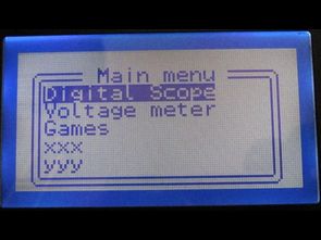
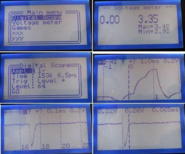
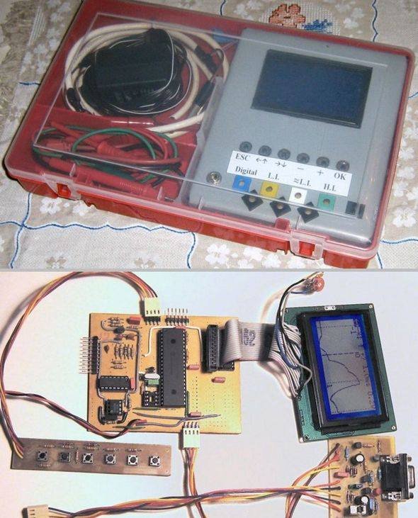
Oscilloscope circuit PIC18F4520 microcontroller based on the indicators used for the 128×64 LCD PCB schematics and source code for the project given all menu.c, etc. glcd.c. in different projects such as files can be useful also to install the bootloader hex program and the circuit shown in Diagram.

LCD OSCILLOSCOPE CIRCUIT (1)

LCD OSCILLOSCOPE CIRCUIT (2)

Source: LCD OSCILLOSCOPE CIRCUIT PROJECT PIC18F4520 alternative: lcd-oscilloscope-circuit-project-pic18f4520.rar alternative link3

The post LCD OSCILLOSCOPE CIRCUIT PROJECT PIC18F4520 appeared first on PIC Microcontroller.

LCD MENU INTERFACE PROJECT PIC18F2620 C18 NOKIA6100

$
0
0

PIC18F2620 Nokia 6100 lcd screen has a lot of Menu interface examples made with made with applications typically microchip PIC series popular in this application is a useful example of how to create a… Electronics Projects, LCD Menu interface Project PIC18F2620 C18 Nokia6100 “microchip projects, microcontroller projects, “

LCD MENU INTERFACE

PIC18F2620 Nokia 6100 lcd screen has a lot of Menu interface examples made with made with applications typically microchip PIC series popular in this application is a useful example of how to create a menu with graphic lcd. Main menu settings, about, has a simple user interface, such as sections. To display images with the “LCD Bitmap And FontCreator” is incompatible with pictures to used


LCD MENU INTERFACE(2)

LCD MENU INTERFACE(1)

The project started pcb diagram of the C source code, “LCD Bitmap FontCreator” program. source: LCD MENU INTERFACE PROJECT PIC18F2620 C18 NOKIA6100 alternative lcd-menu-interface-project-pic18f2620-c18-nokia6100.RAR

The post LCD MENU INTERFACE PROJECT PIC18F2620 C18 NOKIA6100 appeared first on PIC Microcontroller.

LCD SWR METER CIRCUIT PIC16F877

$
0
0

SWR meter circuit pic16f877 microcontroller with lcd display displays the information on a printed circuit board with 2 × 16, schema diagrams in the C source code library files (adc. c, lcd8 c, swrm…. Electronics Projects, LCD SWR Meter Circuit PIC16F877 “microchip projects, microcontroller projects, pic16f877 projects, “

LCD SWR METER CIRCUIT

SWR meter circuit pic16f877 microcontroller with lcd display displays the information on a printed circuit board with 2 × 16, schema diagrams in the C source code library files (adc. c, lcd8 c, swrm. c, timers), and I have 2 different hex code for 16f877a 16f877

SWR METER CIRCUIT FEATURES

Power range 5-100W
Frequency range of 1-30 MHz
SSB operation for the Peak indicator
Forward, backward, power and SWR representation
Simple two-button interface
SWR warning and alarm LEDs

SWR METER CIRCUIT FEATURES (1)

SWR METER CIRCUIT FEATURES (2)

Source: LCD SWR METER CIRCUIT Alternatif link: lcd-swr-meter-circuit-pic16f877.rar

The post LCD SWR METER CIRCUIT PIC16F877 appeared first on PIC Microcontroller.

Displaying Scrolling(Moving) text on 16×2 lcd Using Pic16f877 and Pic18f452 Microcontroller

$
0
0
Displaying moving or scrolling text on lcd(16×2,8×1,16×4,8×2,16×1,20×1,20×2 etc) is very easy using any microcontroller. You just need to know how to efficiently use 16×2 lcd commands. In this project i am using pic 16f877 microcontroller to display text and then scroll it on the 16×2 lcd. The lcd which i am using is 16×2. Where 16 represents number of coulombs and 2 represents number of rows. Text which i am scrolling on the lcd is my website name “microcontroller-project.com“. Code for pic microcontroller is written in c language using mplab-ide with high tech c compiler.

Scrolling/Moving text on lcd with pic microcontroller – Project requirements

  • Pic 16f877 microcontroller
  • 16×2 lcd (I am using.)
  • Potentiometer/variable resistor (To set lcd contrast)
  • crystal(20 MHz)
  • Power supply

If you are newbie and don’t know much about 16×2 lcd working and pin out just go through this simple tutorial. It will explain you about all the pins and functions of 16×2 lcd. 
16×2 lcd pinout and working.
 

Pic microcontroller scrolling text – Project circuit

The circuit of the project is given below. Data pins of 16×2 lcd are directly connected to Port-b of pic microcontroller. The rd(read-write) pin of lcd is connected to port-d pin no 5. The rs(register select) pin of 16×2 lcd is connected to port-d pin 6. The en(enable)pin of 16×2 lcd is connected to port-d pin 7 of pic 16f877 microcontroller. 20 MHz crystal is connected to pin 13 and 14 in parallel to two 33 pf capacitors. Apply 5 volts to pin 1,11&32. Ground pin 12 and 31. Set lcd contrast by rotating potentiometer/variable resistor. 
 
Pic microcontroller scrolling text – Project circuit

Pic microcontroller moving text on lcd – Project code

The code of pic microcontroller scrolling lcd display is written in c language and is easy to understand and modify. First i included the necessary header file #include<htc.h> in code. This header file is necessary to be included if you are using high tech c compiler. Then #define _XTAL_FREQ 20000000 is defining our crystal frequency which is 20 MHz. This crystal frequency is necessary to be defined if you are using __delay_ms() & __delay_us() predefined functions in your code. These predefined functions are used to generate delay in ms() milli seconds and us() microseconds. I made my own delay function so i am not using these predefined functions. Then a character array is initialized. The array size is variable. It contains my website name “microcontroller-project.com“. This is the text which i want to scroll on my 16×2 lcd.  

After the header files now its time to define our functions. First i defined delay function which is used to generate some delay in program execution.Next comes lcd command function.

lcdcmd() function is sending commands to 16×2 lcd. For sending commands first put your command on port-b then select register(to select command register make rs=0). After selecting the command register select which operation you want to perform read or write(for read make rw=1 and write make rw=0). Finally to display character on 16×2 lcd screen give strobe to write command present on data pins of 16×2 lcd. Just make en high(en=1) and after few micro seconds bring it back to low (en=0).

display() functions works in the same way as lcdcmd but with little difference that except command it is writing data on lcd and you just need to select the data register to write data(rs=1 takes you to lcd data register).

lcdint() function is initializing our lcd and pic microcontroller ports. TRISB=0x00 declares pic microcontroller port-b as output port. TRISD5=0,TRISD6=0 & TRISD7=0 are making individual pins of port-d as output. Rest of the commands are initializing our 16×2 lcd. If you want to know about the functions of the commands just go through the tutorial(Link is given at the top after first paragraph). 

In the main function i am displaying text on 16×2 lcd. I start displaying text from first coulomb of row 1 and when my text reaches at the end of the row 1 i start scrolling the text to the left.The statement if(i>=14){lcdcmd(0x18);} is performing this function. When my text reaches to last coulomb of 16×2 lcd which is 15 i start scrolling it to left. The command/statement lcdcmd(0x18) scrolls the text on 16×2 lcd using pic microcontroller.  

I recommend you to please go through the tutorial 16×2 lcd pinout and working if you don’t understand commands and their working. 

   
  #include <htc.h>
  #define _XTAL_FREQ 20000000
  char text[]={microcontroller-project.com };
   
  void delay(unsigned int time) //Time delay function
  {
  unsigned int i,j;
  for(i=0;i< time;i++)
  for(j=0;j< 5;j++);
  }
   
  //Function for sending values to the command register of LCD
  void lcdcmd(unsigned char value)
  {
  PORTB=value;
  RD6= 0; //register select-rs
  RD5 = 0; //read-write-rw
  RD7 = 1; //enable-e
  delay(50);
  RD7=0; //enable-e
  delay(50);
   
  }
  //Function for sending values to the data register of LCD
  void display(unsigned char value)
  {
  PORTB=value;
  RD6= 1; //register select-rs
  RD5= 0; //read-write-rd
  RD7= 1; //enable-e
  delay(500);
  RD7=0; //enable-e
  delay(50);
   
  }
  //function to initialize the registers and pins of LCD
  //always use with every lcd of hitachi
  void lcdint(void)
  {
  TRISB=0x00; //PortB is used as output port
  TRISD5=0;
  TRISD6=0;
  TRISD7=0;
  delay(15000);display(0x30);delay(4500);display(0x30);delay(300);display(0x30);delay(650);
  lcdcmd(0x38); //Character font made is 5×7 matrix
  delay(50);
  lcdcmd(0x0C);
  delay(50);
  lcdcmd(0x01);
  delay(50);
  lcdcmd(0x06);
  delay(50);
  lcdcmd(0x80); //Selects 16×2 lcd coulomb 1 row 1
  delay(50);
  }
   
  void main()
  {
  unsigned int i;
  lcdint();
   
  while(1){
  lcdcmd(0x80);
  lcdcmd(0x01);
  i=0;
  while(text[i]!=\0){
  display(text[i]);
  delay(2000);
  if(i>=14)
  {lcdcmd(0x18);}
  delay(3000);
  i++;
  }
  lcdcmd(0x01);
  delay(5000);
  }
  }
 
Download the project files with code and simulation.The code is written in c language using mplab-ide and high tech c compiler is used to compile the code. Simulation is made in proteaus 8.0. Please give me your feed back on the project. Write your comments below.
In the video below i run the code on 20×4 size lcd. The output is not stable its moving too fast we have to lower the crystal frequency or increase the delay in the code. If you run the same above code on 16×2 lcd the output will be stable and smooth. In-fact the above code is written for 16×2 lcd :D. I just tried to check it on 20×4 to see what happens.   
 

Watch the Project video Here…..

Displaying scrolling text on lcd using pic16f877 microcontroller..

Posted by Microcontroller Projects on Sunday, 24 May 2015

Moving Scrolling Text on lcd using Pic18f452 Microcontroller

Now how to display scrolling text on lcd (16×2) using Pic18f452 microcontroller. The technique is same as stated above for Pic16f877 microcontroller. Only the change is in the code syntax. Code is written in MpLab-IDE. Project files and Proteaus simulation is given below.

In simulation both pic microcontroller codes hex files are given. You can verify both the codes working accurately according to our requirements by running simulation on both the codes hex files separately.  

#include <p18f452.h>
  //#define _XTAL_FREQ 4000000 //Frequency of Oscillator 4MHz
  //_CONFIG_DECL(0x21,0x01,0x00,0x01,0x10,0x0F,0x30,0x0F,0xE0,0x0F,0xF0);
   
  #pragma config OSC = XT
  #pragma config OSCS = OFF
  #pragma config PWRT = OFF
  #pragma config BOR = OFF
  #pragma config BORV = 27
  #pragma config WDT = OFF
  #pragma config WDTPS = 1
  #pragma config CCP2MUX = ON
  #pragma config STVR = OFF
  #pragma config LVP = ON
  #pragma config DEBUG = OFF
  #pragma config CP0 = OFF
  #pragma config CP1 = OFF
  #pragma config CP2 = OFF
  #pragma config CP3 = OFF
  #pragma config CPB = OFF
  #pragma config CPD = OFF
  #pragma config WRT0 = OFF
  #pragma config WRT1 = OFF
  #pragma config WRT2 = OFF
  #pragma config WRT3 = OFF
  #pragma config WRTB = OFF
  #pragma config WRTC = OFF
  #pragma config WRTD = OFF
  #pragma config EBTR0 = OFF
  #pragma config EBTR1 = OFF
  #pragma config EBTR2 = OFF
  #pragma config EBTR3 = OFF
  #pragma config EBTRB = OFF
   
   
  void delay(unsigned int time) //Time delay function
  {
  unsigned int i=0,j=0;
  for(i=0;i< time;i++);
  //for(j=0;j< 2;j++);
  }
   
  //Function for sending values to the command register of LCD
  void lcdcmd(unsigned char value)
  {
  PORTB=value;
  PORTDbits.RD6= 0; //register select-rs
  PORTDbits.RD5 = 0; //read-write-rd
  PORTDbits.RD7 = 1; //enable-e
  delay(50);
  PORTDbits.RD7=0; //enable-e
  delay(50);
   
  }
  //Function for sending values to the data register of LCD
  void display(unsigned char value)
  {
  PORTB=value;
  PORTDbits.RD6= 1; //register select-rs
  PORTDbits.RD5= 0; //read-write-rd
  PORTDbits.RD7= 1; //enable-e
  delay(50);
  PORTDbits.RD7=0; //enable-e
  delay(50);
   
  }
  //function to initialize the registers and pins of LCD
  //always use with every lcd of hitachi
  void lcdint(void)
  {
  TRISB=0x00; //Port B is used as output port
  TRISD=0x05;
   
   
  delay(15000);
  display(0x30);
  delay(4500);
  display(0x30);
  delay(300);
  display(0x30);
  delay(650);
  lcdcmd(0x38); //5×7 Font text will be displayed on lcd
  delay(50);
  lcdcmd(0x0C); //Display on Cursor off
  delay(50);
  lcdcmd(0x01); //Clear LCD (DDRAM)
  delay(50);
  lcdcmd(0x06); //Entry Mode
  delay(50);
  lcdcmd(0x80); //Put Cursor at first line first character space
  delay(50);
  }
   
  void main()
  {
  unsigned int i=0;
  char text[]={I Love Pakistan!!!!!};
   
  lcdint(); //Initialize lcd
   
  while(1){
  lcdcmd(0x80); //Place cursor on first line first character space of lcd
  i=0;
   
  if(PORTDbits.RD0==0){
  PORTDbits.RD1=1;
  for(i=0;i<1000;i++);
  PORTDbits.RD1=0;
  for(i=0;i<1000;i++);
  }
   
  if(PORTDbits.RD2==0){
  while(text[i]!=\0){ //Displaying Text on LCD
  display(text[i]);
  delay(200);
  if(i>=14)
  {
  lcdcmd(0x18); //Moving Display left
  }
  delay(300);
  i++;
  }
  }
  }
  }
 
Both the above codes are performing same functionality. Only the difference is in code statements and syntax. The same circuit diagram given above is for both the code. Nothing is required to be changed in circuit diagram for both the codes.
Visit more text scrolling/moving projects using other microcontrollers. Each project contains its code and circuit diagram in it. All the codes are open source. You can use and modify it according to your needs.

The post Displaying Scrolling(Moving) text on 16×2 lcd Using Pic16f877 and Pic18f452 Microcontroller appeared first on PIC Microcontroller.

Interfacing Graphical LCD(GLCD-JHD12864E) with Microchip PIC16f877 Microcontroller

$
0
0

In this post/tutorial i am going to teach you how to interface graphical lcd jhd12864E with microchip pic16f877 microcontroller. I am going to display my website name “www.microcontroller-project.com” and a special pattern that displays thick lines on dotted graphical lcd display. In graphical lcd name “jhd12864” the number 128×64 means lcd has 128 coulombs and 64 rows. On graphical lcd’s data(character, numbers) is displayed on dots. A joint between coulomb and row is termed as dot. Total dots present in jhd12864 lcd are 128 x 64 = 8192 dots. When dots are combined they make a dot cluster. This cluster of dots in square form is know as matrix. On these 8192 dots we can display/make our data(character, number, image). In graphical lcd’s we are free to make character’s of our desired size unless the size is in the matrix of graphical lcd. 

Before proceeding i would recommend you to please go through a small tutorial. This tutorial will helps you to understand how text is displayed on graphical lcd, how graphical lcd dots are arranged in pages, how graphical lcd is initialized(Graphical Lcd initializing commands), each and every pin of graphical lcd is deeply explained in the tutorial. You can easily understand the code below if you go through the tutorial. 

Interfacing Graphical LCD(GLCD-JHD12864E) with Microchip PIC16f877 Microcontroller

Graphical Lcd with Pic Microcontroller – Project requirements

  • Microcontroller(Microchip Pic16f877)
  • Graphical Lcd(JHD12864E)
  • Crystal (20MHZ)
  • Capacitors (30pf)
  • Potentiometer-Variable resistor(0-100k)
  • Connecting Wires
  • Power Source (Battery, Adapter etc)

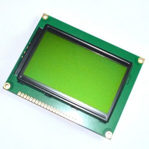
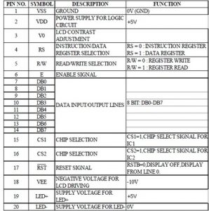
Graphical Lcd which i am using is JHD12864E. It comes in 20 Pin Package. Pin out of JHD12864E is given below. Its an 8-bit lcd. It comes with two built in controllers. Each controller is selected with chip select pins (cs1 and cs2). ​Visit the tutorial link given above to properly understand the pin functions and how to use them properly.

Graphical Lcd with Pic Microcontroller – Project requirements

Graphical lcd with pic microcontroller – Project Circuit Diagram

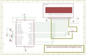
Lcd data pins are connected to Port-B of pic16f877 microcontroller. Lcd is interfaced in 8-bit mode with microcontroller. RS(register select) Pin of Lcd is connected to Port-D pin#7. RW(Read/Write) Pin of Lcd is connected to Port-D Pin#6. EN(Enable) Pin of Lcd is Connected to Port-D pin#5. CS1(Chip select) Pin of Lcd is connected to Port-D pin#4. CS2(Chip select) of lcd is connected to Port-C pin#4. RST(Reset) pin of Lcd is Connected to Port-D pin#2. A variable resistor is used between pins VEE and V0. This variable resistor is very important, it sets the Lcd contrast. Just connect the resistor, vary the resistance by rotating the knob, Adjust the best quality of lcd display that suites you. You can view highly black colour dots by increasing the resistance. If you want to see fant text reduce the resistance. LED+ and LED- are back light pins. I usually switch on the back light same i did for this project.

All other connections are necessary connections to make controller work. Attach crystal(20Mhz) to controller in parallel to two 30pf capacitors. Supply +5v to vcc and vdd. Make GND ground. Circuit diagram of the project is give below.

Graphical lcd with pic microcontroller – Project Circuit Diagram

Coming to code portion. I write code in c++ language and used MPLAB-IDE with High Tech C compiler to compile code and generate Hex code.
  • Clearlcd() function is half-filling each page with dots. Both halfs pages are filled in up and down position. If 2nd page of 1rst half is filled from down then 2nd page of 2nd half is filled from up.
  • #define statements are defining pins as rs,rw,en etc. Now these pins can be accessed in code as rs,rw,en etc.
  • delay() function is used to generate some delay where required.
  • lcdcmd() is sending commands to lcd. It also manipulates lcd pins to successfully execute the command.
  • lcddata() is sending data to lcd. It also manipulates lcd pins to successfully display data on lcd.

Main() function contains the code that displays all stuff on lcd. First it jumps to clearLcd() function fills pages with dots. Then it displays my web site name on lcd. Pattern of each character of my site is commented in the code.

   
  #include<htc.h>
  void clearlcd();
  #define rs RD7
  #define rw RD6
  #define en RD5
  #define cs1 RD4
  #define cs2 RC4
  #define re RD2
   
   
  void delay(unsigned int d){
  unsigned int i,j;
  for(i=0;i< d;i++)
  for(j=0;j< 5;j++);
   
  }
   
  void lcdcmd(char value){
  PORTB=value;
  rw=0;
  rs=0;
  en=0;
  delay(300);
  en=1;
  delay(300);
  en=0;
   
   
  }
   
   
  lcddata(char data1)
  {
  PORTB=data1;
  rw=0;
  rs=1;
  en=0;
  delay(300);
  en=1;
  delay(300);
  en=0;
  }


  void main(){
   
  TRISB=0x00; //Port-B as Output Port
  TRISD=0x00; //Port-D as Output Port
  TRISD=0x00; //Port-D as Output Port
  TRISC=0x00; //Port-C as Output Port
   
   
  delay(300);
  re=1; //Reset disabled
  lcdcmd(0x3E); //Display Off
  lcdcmd(0x3F); //Display on
  lcdcmd(0x3F); //Display on
  clearlcd();
  cs1=1; //Selecting 1 Half
  cs2=0; //Switch off other half
   
   
  lcdcmd(0x3F); //Display on
  lcdcmd(0x40); //Setting y-address
  lcdcmd(0xBB); //Setting x-address page 3 is selected
  lcdcmd(0xC0); //start line
  delay(3000);
  lcddata(0x00); //M
  lcddata(0xFD);
  lcddata(0xFB);
  lcddata(0xF7);
  lcddata(0xFB);
  lcddata(0xFD);
  lcddata(0x00);
  lcddata(0xFF); //M
   
  lcddata(0x0D); //i
  lcddata(0xFF);
   
  lcddata(0xC7); //c
  lcddata(0xBB);
  lcddata(0x7D);
  lcddata(0x7D); //c
  lcddata(0xFF);
   
  lcddata(0x01); //r
  lcddata(0xF7);
  lcddata(0xFB);
  lcddata(0xFD); //r
  lcddata(0xFF);
   
  lcddata(0xC3); //o
  lcddata(0x3D);
  lcddata(0x3D);
  lcddata(0xC3); //o
  lcddata(0xFF);
   
  lcddata(0xC7); //c
  lcddata(0xBB);
  lcddata(0x7D);
  lcddata(0x7D); //c
  lcddata(0xFF);
   
  lcddata(0xC3); //o
  lcddata(0x3D);
  lcddata(0x3D);
  lcddata(0xC3); //o
  lcddata(0xFF);
   
  lcddata(0x01); //n
  lcddata(0xF7);
  lcddata(0xF7);
  lcddata(0x07); //n
  lcddata(0xFF);
   
   
  lcddata(0xF7); //t
  lcddata(0x01);
  lcddata(0x67);
  lcddata(0x7F); //t
  lcddata(0xFF);
   
  lcddata(0x01); //r
  lcddata(0xF7);
  lcddata(0xFB);
  lcddata(0xFD); //r
  lcddata(0xFF);
   
  lcddata(0xC3); //o
  lcddata(0x3D);
  lcddata(0x3D);
  lcddata(0xC3); //o
  lcddata(0xFF);
   
  lcddata(0x01); //l
  lcddata(0x01);
  lcddata(0xFF); //l
   
  lcddata(0x01); //l
  lcddata(0x01);
  lcddata(0xFF); //l
   
  lcddata(0xC7); //e
  lcddata(0xAB);
  lcddata(0x75);
   
  cs1=0; //Switch off First Half
  cs2=1; //Selecting 2nd Half
  lcdcmd(0x3F); //Display on
  lcdcmd(0x40); //Setting y-address
  lcdcmd(0xBB); //Setting x-address page 3 is selected
  //lcdcmd(0xC0); //start line
   
  lcddata(0x79); //e
  lcddata(0xFF);
   
  lcddata(0x01); //r
  lcddata(0xF7);
  lcddata(0xFB);
  lcddata(0xFD); //r
  lcddata(0xFF);
   
   
  lcddata(0xF7); //-
  lcddata(0xF7);
  lcddata(0xF7); //-
  lcddata(0xFF);
   
  lcddata(0x01); //p
  lcddata(0xED);
  lcddata(0xED);
  lcddata(0xF3); //p
  lcddata(0xFF);
   
   
  lcddata(0x01); //r
  lcddata(0xF7);
  lcddata(0xFB);
  lcddata(0xFD); //r
  lcddata(0xFF);
   
   
  lcddata(0xC3); //o
  lcddata(0x3D);
  lcddata(0x3D);
  lcddata(0xC3); //o
  lcddata(0xFF);
   
  lcddata(0xBF); //j
  lcddata(0x7F);
  lcddata(0x05); //j
  lcddata(0xFF);
   
  lcddata(0xC7); //e
  lcddata(0xAB);
  lcddata(0x75);
  lcddata(0x79); //e
  lcddata(0xFF);
   
  lcddata(0xC7); //c
  lcddata(0xBB);
  lcddata(0x7D);
  lcddata(0x7D); //c
  lcddata(0xFF);
   
  lcddata(0xF7); //t
  lcddata(0x01);
  lcddata(0x67);
  lcddata(0x7F); //t
  lcddata(0xFF);
   
  lcddata(0x9F); //.
  lcddata(0x9F); //.
  lcddata(0xFF);
   
  lcddata(0xC7); //c
  lcddata(0xBB);
  lcddata(0x7D);
  lcddata(0x7D); //c
  lcddata(0xFF);
   
  lcddata(0xC3); //o
  lcddata(0x3D);
  lcddata(0x3D);
  lcddata(0xC3); //o
  lcddata(0xFF);
   
  lcddata(0x01); //m
  lcddata(0xFD);
  lcddata(0x01);
  lcddata(0xFD);
  lcddata(0x01); //m
  lcddata(0xFF);
   
  //while(1); //After Printing name remain here for ever……
   
   
  }
   
  void clearlcd()
  {
  unsigned int i=0,j,k;
  int page[]={0xB8,0xB9,0xBA,0xBB,0xBC,0xBD,0xBE,0xBF};
  cs1=1; //First Half is selected
  cs2=0; //Second Half unselected
  lcdcmd(0xC0); //Start line, (64 rows) selects from where to start(1 line)
   
  while(i!=8){
  cs2=0; //Second Half unselected
  cs1=1; //First Half is selected
  lcdcmd(page[i]); //Setting x-address, page is selected
  lcdcmd(0x40); //Setting y-address, coulomb of page is selected
   
  for(j=1;j<=65;j++){
  if(j<=64){
  lcddata(0xF0);
  }
  else if(j==65){
  cs2=1; //Second Half Selected
  cs1=0; //First Half unselected
  lcdcmd(page[i]); //Setting x-address, page is selected
  lcdcmd(0x40); //Setting y-address, coulomb of page is selected
   
  for(k=0;k<=63;k++)
  lcddata(0x0F);
  }
  }
  i=i+1;
  }
  }
Visit next tutorial on how to display Images on GLCD Graphical Lcd with Pic Microcontroller.
Download the project files, folder contains the c code and hex file of the project. Simulation of the project is also included in the folder. Simulation is made in proteaus 8.0. Please give us your feed back on the post. If you have any queries please write them below.
 

The post Interfacing Graphical LCD(GLCD-JHD12864E) with Microchip PIC16f877 Microcontroller appeared first on PIC Microcontroller.


How to Display Text on 16×2 Character Lcd

$
0
0
Displaying Text on 16×1, 16×2 or any size of character lcd is not a complex task. Once you know about the internal structure of the character lcd, lcd pin out, registers associated with lcd’s and CG-RAM(Character Generated RAM) then its all on your finger tips. If you are really interested in lcd programming, and want to know about how to display text on lcd? First take a small tutorial on the Internal Structure of character 16×2 Lcd. Because if you don’t know about internal structure of lcd you will be unable to fully understand the sequence of steps taken to display text on Lcd given below. 

Character lcd can perform both read and write functions. Normally lcds are only used to write text on them. Read operation is performed in few nominal tasks. Below are some steps to display text on lcd. I am going to display Character ‘A’ on lcd.

Displaying Text on 16×2 lcd using microcontroller step by step

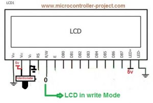
  1. First select the operation which you want to perform ‘Read’ or ‘Write’. Making R/W Pin of Lcd 0(R/W=0) will select the write operation. Now lcd is set in write mode and you can write any text to lcd. If R/W=1 lcd is set in Read mode and you can read data from lcd. Since i want to display ‘A‘ on lcd. I made R/W=0.

Displaying Text on 16×2 lcd using microcontroller step by step

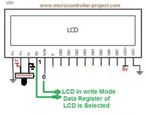
2. Their are two registers in lcd data and command. To display text on lcd you have to select data register of lcd. To execute command you have to select command register of lcd. To select data register make RS=1. To switch to command register make Rs=0. In our case we are displaying text on lcd so make RS=1.

Character Lcd RS(Register Select Pin)

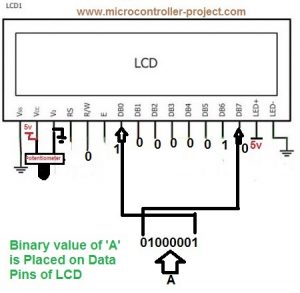
3. Place your text on data pins of Lcd. Since lcd’s data pins are 8-bit wide so place data that is 8-bit wide. Since we want to display ‘A‘ on lcd. ASCII value of ‘A‘ is 65(decimal), 01000001(Binary), 0x41 (Hexadecimal). Place this value on lcd data pins. 

Character Lcd data pins. Data Placed on Data Pins

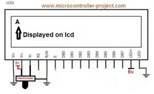
4. Now make en=1 and after some microseconds again make en=0. This en signal gives a push to data placed in data register or on data pins to display on 16×2 screen.

Text Displayed on Character lcd

To display next character repeat the above steps again.To make lcd fully functional you first have to initialize lcd. By initialization i mean set the font of character, decide the cursor(Blinking or not blinking) select the position where you want to display character etc. These parameters are set by sending commands to lcd. Standard lcd commands and their functions are given in the link below.


Note: To execute commands steps are same like to display text only difference is in the RS pin selection. To execute commands you have to select the command register of lcd. Make RS=0 to select command register of lcd. Now your commands goes to command register and you can execute them by make en=1 and back to en=0.

Simple text display on 16×2 lcd demo project using 8051 microcontroller

In this project i will display my name “USMAN ALI BUTT” on both rows of 16×2 lcd. First my name will appear on first row of 16×2 lcd. Then after some time it disappears and re appears on second line of 16×2 lcd. The project is really simple.
Hardware requirements
  • 16×2 character lcd.
  • 89c51 or 89c52 microcontroller.
  • Bread board large enough to make circuit on it
  • 5 volts DC power supply.
  • Potentiometer for setting lcd contrast.
  • Software for codding, keil etc
  • Burner to burn code in the microcontroller

Dispay text on 16×2 lcd – Project code

The circuit for the project is simple. Connect Port-1 of your 8051(89c51,89c52) microcontroller to 8 data pins of the lcd. The pins should interface the microcontroller in the order that pin#1 of Port-1 is connected to pin#1 of data pin on lcd. Pin#2 of Port-1 of 8051 to pin#2 of lcd and so on up till pin 8. Connect pin#5 of Port-3 to rs(register select) pin of lcd. pin#7 of microcontroller Port-3 to rw(read write) pin of lcd and pin#6 of microcontroller Port-3 to en(enable) pin of lcd. ​

Rest of the connections are same as we made in all of our circuits apply 5 volts to vcc pin#40 and Pin#31 of 8051(89c51,89c52). Ground pin#20. Attach crystal of 11.0592MHz frequency in parallel to two 33pf capacitors to pin#18(XTAL1) and Pin#19(XTAL2) of microcontroller. You can also use crystal of any other frequency if you want and capacitors with them can very from 27pf to 33pf.
 
Displaying Text on Character Lcd with 8051(89c51,89c52) microcontroller
 
#include<reg51.h>
  sbit rs=P3^5; //Register select (RS)
  sbit rw=P3^7; //Read write (RW) pin
  sbit en=P3^6; //Enable (EN) pin
  void delay(unsigned int time) //Time delay function
  {
  unsigned int i,j;
  for(i=0;i< time;i++)
  for(j=0;j<5;j++);
  }
  //Function for sending Commands to the command register of LCD
  void lcdcmd(unsigned char value)
  {
  P1=value;
  //P3=0x40;
  rw=0;
  rs=0;
  en=1;
  delay(50);
  en=0;
  delay(50);
  return;
  }
  //Function for sending data to the data register of LCD
  void display(unsigned char value)
  {
  P1=value;
  //P3=0x60;
  rw=0;
  rs=1;
  en=1;
  delay(500);
  en=0;
  delay(50);
  return;
  }
  //Function to initialize the registers and pins of LCD
  //always use with every lcd of hitachi
  void lcdint(void) //Function sending commands to lcd. To initialize lcd
  {
  P1=0x00;
  P3=0x00;
  delay(15000);display(0x30);delay(4500);display(0x30);delay(300);
  display(0x30);delay(650);lcdcmd(0x38);delay(50);lcdcmd(0x0F);
  delay(50);lcdcmd(0x01);delay(50);lcdcmd(0x06);delay(50);lcdcmd(0x80);
  delay(50);
  }
  //MAIN FUNCTION
  void main()
  {
  int i,j,k=0,l=0,s=0;
  char u[]={USMAN ALI BUTT};
  char sec[]={JUMPING TO SECOND LINE};
  lcdint(); //Initialize Lcd
  lcdcmd(0x01); //Clear Lcd Command
  lcdcmd(0x80);
  while(u[k]!=\0)
  {
  display(u[k]);
  k++;
  }
  delay(100000);
  lcdcmd(0x01); //Clear all contents of lcd
  lcdcmd(0x80); //Initialize Cursor to first character matrix of lcd
  while(sec[s]!=\0)
  {
  if(s==15)
  lcdcmd(0xC0); //Initializing Cursor to second line first Character matrix
  display(sec[s]);
  s++;
  }
  delay(100000);
  lcdcmd(0x01);
  lcdcmd(0xC0); //Initializing Cursor to second line first Character matrix
  while(u[l]!=\0)
  {
  display(u[l]); //Printing same string on second line
  l++;
  }
  delay(100000);
  }
 
More Projects related to displaying Text On 16×2 lcd are given below. Each project is made using different type of microcontroller, arduino pic microcontroller etc. Projects are open source. You can use and edit code according to your need.
 

To learn difference between sending commands and data to lcd click. Difference between sending commands and data to lcd. If you feel any difficulties in code just leave a comment regarding your problem. I will definitely figure it out.

Source: How to Display Text on 16×2 Character Lcd

The post How to Display Text on 16×2 Character Lcd appeared first on PIC Microcontroller.

Interfacing JHD404A (40×4) lcd with Microcontroller

$
0
0

This post covers how to interface JHD404A 40×4 lcd with microcontroller (89c51, Pic16f877, Arduino etc). JHD404A is a 40×4 Character lcd. 40×4 means it has 40 coulombs and 4 rows. On each row of lcd we can display 40 characters/numbers etc. Total characters which we can display on 40×4 lcd is equal to (40×4=160) 160.

Like all other character lcd’s JHD404A also has a controller in it which controls its internal functions. 40×4 contains HD44780 lcd controller by hitachi in it. Which means same commands are used to initialize 40×4 lcd that are used to initialize 8×1, 16×1, 16×2 ,20×2 character lcd’s. The only difference between JHD404A and his siblings when compared is, it has two enable pins (en1 & en2). This is because a single HD44780 controller can handle up to 80 characters. To handle 160 characters we need an extra HD44780 controller. ​

Why two enable ports?

Consider a 40×1 or 40×2 lcd they have one enable (en) pin. In contrary to 40×1 and 40×2, 40×4 lcd has two enable (en1 & en2) pins. Actually 40×4 is comprised of two 40×2 lcd’s stacked on each other. We have to initialize 40×4 lcd two times. One initializing is using en1 pin and second is using en2 pin. We have to initialize both HD44780 controllers. First two rows of 40×4 lcd are initialized using en1 pin and then third fourth rows are initialized using en2 pin.
 
Why two enable ports
Some tutorials which might help you if you are new and don’t know much about character lcd’s and their working. These tutorials will help you in understanding this post.
I made a PLC(programmable logical controller) in which i used 40×4 lcd to show input and output status. You can also build yours just take a look at it its not a hard task.

Interfacing JHD404A (40×4) Lcd with 89c51 Microcontroller

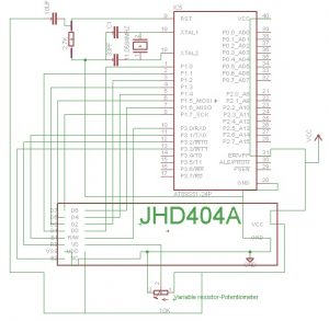
Interfacing 40×4 lcd with 8051 series microcontrollers is not a hard task. If you have already done interfacing of any other character lcd with 8051 microcontrollers you can easily interface 40×4 lcd with 89c51. I made a simple project the circuit diagram is below.
 
Interfacing JHD404A (40×4) Lcd with 89c51 Microcontroller
 
#include <reg52.h>
  sbit rw =P3^0; //Read/Write Pin
  sbit en1=P3^1; //Enable for First 80 Characters
  sbit rs =P3^2; //Register select (RS)
  sbit en2=P3^3; //Enable for Second 80 Characters
   
   
  void delay(unsigned int time) //Time delay function
  {
  unsigned int i,j;
  for(i=0;i< time;i++)
  for(j=0;j< 5;j++);
  }
   
  //Function for sending values to the command register of LCD
  void lcdcmd1(unsigned char value)
  {
  P1=value;
  rs = 0;
  rw = 0;
  en1 = 1;
  delay(50);
  en1=0;
  delay(50);
   
  }
  //Function for sending values to the command register of LCD
  void lcdcmd2(unsigned char value)
  {
  P1=value;
  rs = 0;
  rw = 0;
  en2 = 1;
  delay(50);
  en2=0;
  delay(50);
   
  }
  //Function for sending values to the data register of LCD
  void display1(unsigned char value)
  {
  P1=value;
  rs = 1;
  rw = 0;
  en1 = 1;
  delay(500);
  en1=0;
  delay(50);
   
  }
  //Function for sending values to the data register of LCD
  void display2(unsigned char value)
  {
  P1=value;
  rs = 1;
  rw = 0;
  en2 = 1;
  delay(500);
  en2=0;
  delay(50);
   
  }
  //function to initialize the registers and pins of LCD
  //always use with every lcd of hitachi
  void lcdint1(void)
  {
  P1=0x00;
  P3=0x00;
  delay(15000);
  display1(0x30);
  delay(4500);
  display1(0x30);
  delay(300);
  display1(0x30);
  delay(650);
  lcdcmd1(0x38);
  delay(50);
  lcdcmd1(0x0F);
  delay(50);
  lcdcmd1(0x01);
  delay(50);
  lcdcmd1(0x06);
  delay(50);
  }
   
  void lcdint2(void)
  {
  P1=0x00;
  P3=0x00;
  delay(15000);
  display2(0x30);
  delay(4500);
  display2(0x30);
  delay(300);
  display2(0x30);
  delay(650);
  lcdcmd2(0x38);
  delay(50);
  lcdcmd2(0x0F);
  delay(50);
  lcdcmd2(0x01);
  delay(50);
  lcdcmd2(0x06);
  delay(50);
  }
   
  void main()
  {
   
  unsigned int count=0;
  char st[]=Its 40×4 Lcd microcontroller-project.com;
  P1=0x00; //Port-1 as Output
  P3=0x00; //Port-2 as Output
  lcdint1();
  lcdint2();
   
   
  while(1){
  lcdcmd1(0x80);
  while(count!=40){
  display1(st[count]);
  count++;
  }
  count=0;
  delay(5);
  lcdcmd1(0xC0);
  while(count!=40){
  display1(st[count]);
  count++;
  }
  count=0;
  delay(5);
  lcdcmd2(0x80);
  while(count!=40){
  display2(st[count]);
  count++;
  }
  count=0;
  delay(5);
  lcdcmd2(0xC0);
  while(count!=40){
  display2(st[count]);
  count++;
  }
  count=0;
  }
  }
   

Download the project code, folder includes the full keil uvision 4 project files and hex code. Please give us your feed back on the project.

Source: Interfacing JHD404A (40×4) lcd with Microcontroller

The post Interfacing JHD404A (40×4) lcd with Microcontroller appeared first on PIC Microcontroller.

How to display 5×8 and 5×10 size font characters on 16×2 lcd with 8-bit microcontrollers

$
0
0

Character lcds can display character of font size 5×8 and 5×10. In 5xn, 5 represents number of coulombs and N represents number of rows. Character lcd’s especially which are controlled by Hitachi HD44780 controller can display 5×8 and 5×10 size font character. Some lcd’s can only display character in 5×8 font. In this project i am going to teach you how to display characters of font size 5×8 and 5×10 on character lcd?

If you are newbie and don’t know about internal structure of character lcd and how to interface it with microcontrollers? Than i suggest you you first take the getting started with lcd tutorial.

As you know first we have to initialize the lcd that we are using (8×1, 8×2, 8×4, 16×1, 16×2, 16×4, 20×1, 20×2, 20×4, 24×1, 24×2, 24×4, 32×1, 32×2, 40×1, 40×2, 40×4). By initialization I mean 

  • Should the cursor appears on lcd or not? If appearing, whether it should be blinking or normal?
  • What should be the size of character-font appearing on lcd (5×8, 5×10)?

To learn about lcd initialization standard commands go through the simple tutorial below. 

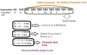
We are going to discuss only commands that are related to character size Font-matrix in this tutorial. To initialize character lcd we have to send commands to command-register of lcd. All the commands are 8-bit in nature. For Initializing character font size, 8-bit commands individual bits represents.

How to display 5×8 and 5×10 size font characters on 16×2 lcd with 8-bit microcontrollers

  • DL selects lcd mode. 8-bit or 4-bit. Don’t know Go through the tutorial(Lcd in 4-bit and 8-bit mode)
  • N selects if lcd contains 2 rows or 1.
  • F selects character font size. (5×8 or 5×10)

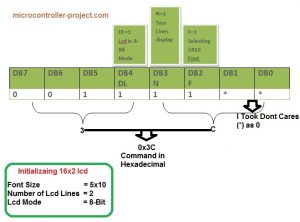
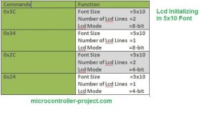
Now if I have a 16×2 lcd and i want to initialize its Character font to be 5×10 my command will be.

5x10-character-size-initializing-command-for-16x2-lcd_orig

Standard Lcd Commands for 5×10 Display

Standard Lcd Commands for 5×10 Display

Now i am going to display characters on lcd in 5×8 and 5×10 font. I am going to print it on lcd using two different microcontrollers. Microchip pic16f877 and 8051(89c51,89c52) microcontroller. 

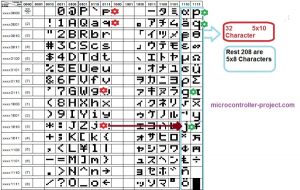
  • You can display 208 characters in 5×8 font and 32 characters in 5×10 font. Total ASCII characters present in HD44780 lcd controller are 240. In which 208 are in 5×8 font and 32 are in 5×10 font. 
  • In CG-RAM you can create 8 custom characters at a time in 5×8 font and 4 custom characters in 5×10 font. Don’t know about CG-RAM and custom characters? Go through(CG-RAM & custom characters generation and display)

See the difference in the same characters in same row, marked against red and green star. red star represents 5×8 font size character and green represents same character with 5×10 size font. Picture taken from hd44780 controller data sheet.

lcd 5×8 and 5×10 size characters present in hd44780 controller ascii set

Displaying 5×10, 5×8 font size Characters on character lcd Using PIC16f877 Microcontroller.

  Project Requirements
  • PIC 16f877 microcontroller
  • 16×2 lcd
  • Potentiometer (To set Lcd Contrast)
  • Crystal (20 MHz)
  • Capacitors 33Pf

I am going to print/display G,J,P & Q in 5×8 and 5×10 font. These characters are present in HD44780 Controller in 5×8 and 5×10 font. I will call their addresses and they will appear/display on lcd screen. 

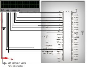
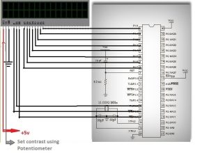
Lcd data pins are Connected to Port-B of microcontroller. Lcd control pins (en,rs,rw) are connected to Port-D Pins#7,6,5. Rest of the connections are normal connections. Supplying power to microcontroller. Grounding GND pin. Connecting Crystal to microcontroller etc. Circuit diagram of the project is given below.

Code is written in Mp-Lab ide and high tech c compiler is used to compile the code. Pic kit-2 is used to upload the code to microcontroller.

/**************************************************
* Property of: www.microcontroller-project.com *
* Author: Usman Ali Butt *
* Created on 11 April, 2015, 2:30 PM *
**************************************************/
#include <htc.h>
#define _XTAL_FREQ 20000000
#define en RD7
#define rs RD6
#define rw RD5

void delay(unsigned int time) //Time delay function
{
unsigned int i,j;
for(i=0;i< time;i++)
for(j=0;j< 3;j++);
}
//Function for sending values to the command register of LCD
void lcdcmd(unsigned char value)
{
PORTB=value;
rs= 0; //register select-rs
rw = 0; //read-write-rd
en = 1; //enable-e
delay(50);
en=0; //enable-e
delay(50);
}
//Function for sending values to the data register of LCD
void display(unsigned char value)
{
PORTB=value;
rs= 1; //register select-rs
rw= 0; //read-write-rd
en= 1; //enable-e
delay(500);
en=0; //enable-e
delay(50);
}
//function to initialize the registers and pins of LCD
//always use with every lcd of hitachi
void lcdint(void)
{
TRISB=0x00; //Port B is used as output port-connected to lcd
TRISD5=0; //Lcd controlling pins
TRISD6=0; //Lcd controlling pins
TRISD7=0; //Lcd controlling pins
delay(15000);
display(0x30);
delay(4500);
display(0x30);
delay(300);
display(0x30);
delay(650);
lcdcmd(0x3C); //5×10 Font Selected
delay(50);
lcdcmd(0x0C); //Display on Cursor off
delay(50);
lcdcmd(0x01); //Clear Lcd
delay(50);
lcdcmd(0x06); //Entry Mode, Increment Cursor Automatically
delay(50);
lcdcmd(0x80); //Control set at Lcd 1 Row, 1 Coulomb
delay(50);
}

void main()
{
lcdint(); //Initialize Lcd
display(0xea);//Display 5×10 J
display(0x6a);//Display 5×8 j
display(‘ ‘);
display(0x67);//Display 5×8 g
display(0xe7);//Display 5×10 G
display(‘ ‘);
lcdcmd(0xC0);
display(0x70);//Display 5×8 p
display(0xf0);//Display 5×10 P
display(‘ ‘);
display(0x71);//Display 5×8 q
display(0xf1);//Display 5×10 Q
while(1);
}

D​isplaying 5×10, 5×8 Characters on 16×2 lcd Using 8051(89c51, 89c52) Microcontroller.

 Project Requirements
  • 8051(89c51,89c52) series microcontroller
  • 16×2 lcd
  • Potentiometer (To set Lcd Contrast)
  • Crystal (11.0592 MHz)
  • Capacitors 33Pf

Lcd data pins are connected to Port-1 of microcontroller. Lcd controlling pins en,rs,rw are connected to Port-3 pins#5,6,7. Circuit diagram of the project is given below.

D​isplaying 5×10, 5×8 Characters on 16×2 lcd Using 8051(89c51, 89c52) Microcontroller.

Code is almost same like of the pic microcontroller. Only the syntax of the code is changed. Code is written in keil u-vision ide.

/**************************************************
* Property of: www.microcontroller-project.com *
* Author: Usman Ali Butt *
* Created on 13 April, 2015, 2:30 PM *
**************************************************/
#include<reg51.h>
sbit rs=P3^5; //Register select (RS)
sbit rw=P3^7; //Read write (RW) pin
sbit en=P3^6; //Enable (EN) pin

void delay(unsigned int time) //Time delay function
{
unsigned int i,j;
for(i=0;i< time;i++)
for(j=0;j< 5;j++);
}

//Function for sending values to the command register of LCD
void lcdcmd(unsigned char value)
{
P1=value;
P3=0x40;
delay(50);
en=0;
delay(50);
return;
}
//Function for sending values to the data register of LCD
void display(unsigned char value)
{
P1=value;
P3=0x60;
delay(500);
en=0;
delay(50);
return;
}
//function to initialize the registers and pins of LCD
//always use with every lcd of hitachi
void lcdint(void)
{
P1=0x00; //Port-1 as output
P3=0x00; //Port-3 as output
delay(15000);
display(0x30);
delay(4500);
display(0x30);
delay(300);
display(0x30);
delay(650);
lcdcmd(0x3C); //5×10 Font Selected
delay(50);
lcdcmd(0x0C); //Display on Cursor off
delay(50);
lcdcmd(0x01); //Clear Lcd
delay(50);
lcdcmd(0x06); //Entry Mode, Increment Cursor Automatically
delay(50);
lcdcmd(0x80); //Control set at Lcd 1 Row, 1 Coulomb
delay(50);
}

//MAIN FUNCTION
void main()
{
lcdint(); //Initialize Lcd
display(0xea);//Display 5×10 J
display(0x6a);//Display 5×8 j
display(‘ ‘);
display(0x67);//Display 5×8 g
display(0xe7);//Display 5×10 G
display(‘ ‘);
lcdcmd(0xC0);
display(0x70);//Display 5×8 p
display(0xf0);//Display 5×10 P
display(‘ ‘);
display(0x71);//Display 5×8 q
display(0xf1);//Display 5×10 Q
while(1);
}

Source: How to display 5×8 and 5×10 size font characters on 16×2 lcd with 8-bit microcontrollers

The post How to display 5×8 and 5×10 size font characters on 16×2 lcd with 8-bit microcontrollers appeared first on PIC Microcontroller.
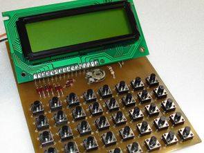
Displaying Images on Graphical Lcd(JHD12864E) using Pic16f877 Microcontroller

$
0
0

Here in this post/tutoriqal i am going to teach you how to display images on Graphical lcd using Pic Microcontroller(pic16F877). I am using JHD12864E graphical LcD in my Project. JHD12864E is 128×64 dimension lcd. 128×64 means it has 128 coulombs and 64 rows. So total dots it has is 128×64=8192. You can display an image of maximum size(Dimension = 128×64) with in this range. Some notable things before starting the tutorial.

  • You can only display images of .bmp format. Images bitmaps are obtained only by .bmp format. Graphical lcds consists of dots, we have to display our images on these dots and .bmp image is also comprised of dots. So can easily find bits of images of .bmp format and can map them on Graphical lcd.
  • You can only display black and white images(Monochrome images bitmap is hard to generate. No software is found for generating bitmap of monochrome images on internet).
  • If you want to display images of size greater than 128×64 than first change the size of the image. I used an online image dimension converter(My image size is 960×1280. I converted it to 128×64 using an online image dimension converter. You can found many tools to convert images just Google for it).  

If you are new to graphical lcd and didn’t know much about it just go through the tutorial below. You will become familiar with graphical lcd, its half and pages, its commands, its pin out and how to effectively use it. It will help you in understanding the code given below.

I am going to display five images on graphical lcd. Images which i am going to display on lcd are below. I created bitmaps of all the images given below.

Displaying Images on Graphical Lcd(JHD12864E) using Pic16f877 Microcontroller

The first pic which i am going to display is mine(The Admin). Its original size is 960×1280, format is .jpg and its a monochrome pic. I converted it to black and white, format .bmp and size is reduced to 128×64 using an online software for image editing.

Now when you converted images its time to find bitmaps. Bitmaps are found using special software’s. I used an open source software The Dot Factory. Just give the path of the image and click generate it will generate bitmap with in a second. Download the software from here.

Dot factory not only generates bitmaps it also gives you the dimension of the newly generated bitmaps. Once bitmaps code is generated you can copy them from their and place them in your code. 
Pic16f877 microcontroller is used to display images on jhd12864E graphical lcd. Port-B is used to send data and commands to graphical lcd. It is connected to data pins D0-D7 of Graphical lcd. Lcd controlling pins en(Enable),rs(Register-select),rw(read-write) are connected to Port-D pins#7,6,5. Graphical lcd’s First-Half selection line is connected to Port-D Pin#4 and second-half selection line is connected to Port-C Pin#4. Circuit diagram of the project is given below.

Source: Displaying Images on Graphical Lcd(JHD12864E) using Pic16f877 Microcontroller

The post Displaying Images on Graphical Lcd(JHD12864E) using Pic16f877 Microcontroller appeared first on PIC Microcontroller.

How to interface 16×2 LCD in 4-bit mode with PIC Microcontroller (PIC18F4550)

$
0
0

The 16×2 character LCD can work in two modes, namely, 8-bit and 4-bit. These modes basically correspond to the number of data pins used in interfacing LCD. 8-bit mode uses all the data lines and has been explained in LCD interfacing with PIC18F4550. In 4-bit mode, only four data pins of LCD are connected to the controller. This mode, thus, saves four pins of the controller unlike 8-bit mode. The configuration and display method of LCD in 4-bit mode has been explained here.

The 8-bit mode of LCD interfacing with PIC has been explained earlier. In the 4-bit mode the (8-bit) data/command is sent in nibble (four bits) format to LCD. The higher nibble is sent first followed by the lower nibble. In 4-bit mode only four data pins (D4-D7) of LCD are connected to the controller. The control pins (RS, RW and EN) are connected the same way as in 8-bit mode. The connections of LCD with PIC18F4550 are shown in the adjoining circuit diagram. Please note that here only PortB is used to connect data lines as well as control lines unlike in 8-bit mode. Refer LCD interfacing with PIC in 8-bit mode.

LCD is configured for 4-bit mode by sending appropriate instruction known as Function Set. The Function Set is hexadecimal instruction for LCD MPU unit which selects the working modes of LCD. The Function Set is given below along with its description. 
Instruction
RS
RW
D7
D6
D5
D4
D3
D2
D1
D0
Function Set
0
0
0
0
1
DL
N
F
 
Description: 
DL       –           Data Length               
N         –           No. of Lines               
F          –           Font                           
 
 Value
 DL
 N
F
1
8 bit
2 lines
5×10 dots
0
4 bit
1 line
5×7 dots
 
Fig. 2: Bit Values to Configure LCD in 4-bit mode with PIC18F4550 
 
According to the table, the value of Function Set for 4–bit mode will be [ 0010 0000 ] 0x20. The value of Function Set for the LCD configuration : 2 line (N=1), 5×7 dots (F=0) and 4-bit (DL=0) mode will be [ 0010 1000 ] 0x28.
 
It is important to note that when the power supply is given to LCD, it remains in 8-bit mode. In this state if 0x20 is sent, lower nibble will not be received by LCD because only four data lines (D4-D7) are connected, so 0x02 is sent instead of 0x20.
 
For more details on nibble arrangement and bit shifting, refer LCD 4-bit mode with AVR.

Project Source Code

###

// Program to interface 16×2 LCD with PIC18F4550 Microcontroller using 4-bit mode

// Configuration bits
/* _CPUDIV_OSC1_PLL2_1L, // Divide clock by 2
_FOSC_HS_1H, // Select High Speed (HS) oscillator
_WDT_OFF_2H, // Watchdog Timer off
MCLRE_ON_3H // Master Clear on
*/

//LCD Control pins
#define rs LATA.F0
#define rw LATA.F1
#define en LATA.F2

//LCD Data pins
#define lcdport LATB

void lcd_ini();
void dis_cmd(unsigned char);
void dis_data(unsigned char);
void lcdcmd(unsigned char);
void lcddata(unsigned char);

void main(void)
{
unsigned char data0[]=”EngineersGarage”;
unsigned int i=0;
TRISB=0; // Configure Port B as output port
LATB=0;
lcd_ini(); // LCD initialization
while(data0[i]!=”)
{
dis_data(data0[i]);
Delay_ms(200);
i++;
}
}
void lcd_ini()
{
dis_cmd(0x02); // To initialize LCD in 4-bit mode.
dis_cmd(0x28); // To initialize LCD in 2 lines, 5×7 dots and 4bit mode.
dis_cmd(0x0C);
dis_cmd(0x06);
dis_cmd(0x80);
}

void dis_cmd(unsigned char cmd_value)
{
unsigned char cmd_value1;
cmd_value1 = (cmd_value & 0xF0); // Mask lower nibble because RB4-RB7 pins are being used
lcdcmd(cmd_value1); // Send to LCD
cmd_value1 = ((cmd_value<<4) & 0xF0); // Shift 4-bit and mask
lcdcmd(cmd_value1); // Send to LCD
}

void dis_data(unsigned char data_value)
{
unsigned char data_value1;
data_value1=(data_value&0xF0);
lcddata(data_value1);
data_value1=((data_value<<4)&0xF0);
lcddata(data_value1);
}

void lcdcmd(unsigned char cmdout)
{
lcdport=cmdout; //Send command to lcdport=PORTB
rs=0;
rw=0;
en=1;
Delay_ms(10);
en=0;
}

void lcddata(unsigned char dataout)
{
lcdport=dataout; //Send data to lcdport=PORTB
rs=1;
rw=0;
en=1;
Delay_ms(10);
en=0;
}

###

Circuit Diagrams

Circuit-Diagram-of-How-to-interface-16×2-LCD-in-4-bit-mode-with-PIC-Microcontroller-PIC18F4550

Project Components

Project Video

Source: How to interface 16×2 LCD in 4-bit mode with PIC Microcontroller (PIC18F4550)

The post How to interface 16×2 LCD in 4-bit mode with PIC Microcontroller (PIC18F4550) appeared first on PIC Microcontroller.

Viewing all 253 articles
Browse latest View live


<script src="https://jsc.adskeeper.com/r/s/rssing.com.1596347.js" async> </script>