Quantcast
Channel: LCD Projects - PIC Microcontroller
Viewing all 253 articles
Browse latest View live

PIC12F675 LCD Interfacing Code and Proteus Simulation

$
0
0

This post provides the LCD[1] interfacing code using PIC12F675 microcontroller. This code is written in C language using MPLAB with HI-TECH C compiler. You can download this code from the ‘Downloads‘ section at the bottom of this page.

PIC12F675 LCD Interfacing

It is assumed that you know how to make an LED blink with PIC12F675 microcontroller. If you don’t then please read this page first, before proceeding with this article.

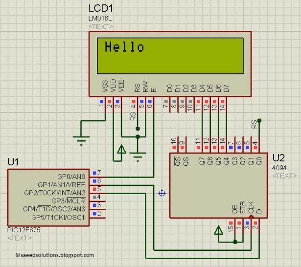
PIC12F675 microcontroller has only 6 IO pins ( 5 of them can be made input or output, but pin4 (GP3) can only be made an input ). So it is not possible to directly attach LCD with PIC12F675 even in 4bit mode[2]. To make this possible, a serial to parallel shift register IC (4094) is used in this circuit. In this way by only using 3 pins of PIC12F675 microcontroller, we can interface LCD with it in 4bit mode. This is shown below in the figure.

In the above figure, GP0 pin is being used as Enable pin for LCD. GP1 pin is used as Clock pin and GP2 pin is used as Data pin for 4094 IC.

PIC12F675 LCD Interfacing schematic

Code

In the code you can easily select pins to be used for interfacing with the LCD. Following figure shows the pin selection code.

Downloads

LCD interfacing code using PIC12F675 was compiled in MPLAB v8.85 with HI-TECH C v9.83 compiler and simulation was made in Proteus v7.10. To download code and Proteus simulation click here.


For more detail: PIC12F675 LCD Interfacing Code and Proteus Simulation

The post PIC12F675 LCD Interfacing Code and Proteus Simulation appeared first on PIC Microcontroller.


pic18f2550 Microcontroller Project Board

$
0
0

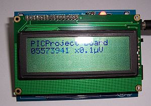
The new PIC18F2550 Project Board was designed as the development platform for student projects.
board lcd
The board features

MCU: PIC18F2550 with external xtal,
ADC: one channel 0-2.5V sigma-delta converter, Linear Technology LTC2400/LTC2420,
6-channal 10-bit ADC 0-5V,
Display: Two connectors for text LCD or GLCD,
USB: onchip USB port with type B connector,
Power supply: onboard low dropout regulator, rechargeable battery,
Code programming: 10-pin header for In Circuit Loader.

The board platform is suitable for developing the microcontroller based instrumentation. Students may build the signal conditioning board, plugs it to PIC project board, develops the code and programs it with loader cable easily.

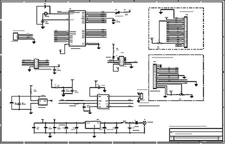
schematic circuit

Hardware

The MCU is 28-pin PIC18F2550 with external xtal as the option. We can use internal oscillator. The loader uses only three pins, PGD, PGC and MCLR. J1 is ICSP header, we can plug it to the application board for both code loading and running. The user I/O ports is 6-channel analog input RA0-RA5. PORTB, RB0-RB7 is for LCD interface. User can choose either text LCD at JR1 connector or GLCD at JF1 connector. PORTC, RC0-RC2 is used to interface the LTC2400/LTC2420 SPI bus, sigma delta converter. RC4 and RC5 is USB port signal. RC6 is also available at J2. RC7 is debug LED. J1 is ICSP header. D2 protects VCC from high voltage programming at MCLR pin. U2 can be 20-bit or 24-bit resolution, sigma-delta converter, LTC2420 or LTC2400. J3 is jumper for selecting rejection of the common mode noise frequency, 50Hz or 60Hz. The reference voltage, +2.5V is generated by U3 LM336. The board can be powered by rechargeable battery, BT1.

For more Detail: pic18f2550 Microcontroller Project Board

The post pic18f2550 Microcontroller Project Board appeared first on PIC Microcontroller.

Driving LCD directly from PIC

$
0
0

This project is one another thermometer application that uses the TCN75A digital sensor from Microchip. The sensor provides digital temp conversion in the range -40°C – 125°C (-40°F – 257°F) and has maximum resolution 0.0625°C. However, the LCD that I used (2.5 digits model LCD-S2X1C50TR manufactured by Lumex) only works reliably in the temperature range 0 – 50°C, so the code is adjusted for this range only. The temperature is displayed in degrees of Fahrenheit.

This note describes the approach and software. Check here for practical implementation of these ideas.

Also check here for a really low-power thermometer.

Hardware

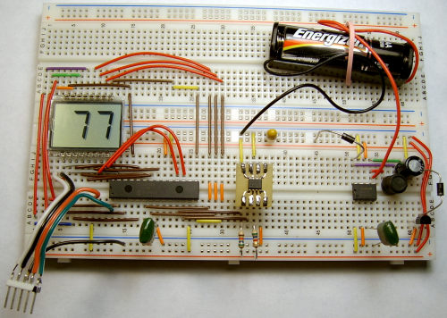
The schematic can be easily obtained from the image below. The LCD is a passive device and has no built-in controller. The used microcontroller PIC16F913 has a built-in LCD module that is able to generate all necessary waveforms for driving LCDs with up to 16 segments (plus up to four backplanes). The above mentioned LCD assumes a simple static mode that requires only one BIAS voltage of 5V and, hence, has just one backplane. The LCD has 16 pins, out of which 2·7 = 14 are used for two 7-segment digits, one is for the leftmost 1/2-digit (can only be 1, its both segments are connected together internally) and one is for the backplane (the remaining pin RC5/SEG10 is not used for LCD in my design). This way 16 out of 25 I/O pins are reserved for driving LCD and two more pins are used for communicating with the temp sensor that implements the I2C interface. The PIC has this interface also implemented in hardware. However, unfortunately this block cannot be used along with the LCD driver, since they share the same I/O pins. Driving the LCD is a more important function for me, while a small subset of the I2C interface needed to communicate with the sensor can be easily implemented in software. The unused for the thermometer I/O pins RA2, RA6, RA7, BR5, and RC5 are configured for output to minimize the power consumption. The input only pin RE3 is used here for programming. Hence, there is a good number of free pins available for other applications of this PIC which involve LCD.

Prototype Layout

Driving LCD directly from PIC

The sensor is connected to the PIC via pins RC0/VLCD1 and RC1/VLCD2. Normally, these pins are used for the LCD BIAS voltages in a non-static mode. However, it turns out that they are just normal I/O pins in the LCD static mode, which is not clear from the documentation and discovered experimentally. The 5-pin connector in the left bottom corner of the image is intended for PIC programming by using the ICSP (In-Circuit Serial Programming) mode and goes to my Brenner8 USB programmer during programming only. The components on the right part of the image around MAX756 chip belong to the DC-DC converter that delivers 5V voltage from a single 1.5V battery. The TCN75A sensor is put on a small PCB for a convenience. The two pulling-up resistors of the I2C bus are 5.6K each.

Software

The code starts with four subroutines used for LCD 7-segment codes. The pin assignment between the LCD and PIC is based on a convenient PCB layout (this part of the project is not completed yet). This lead to the situation that both LCD digits are driven from different parts of the PIC LCD Data registers, so four 7-segment codes are needed to update the LCD digit-by-digit. All variables used in the code are placed in the shared area of all banks, thus minimizing the switching between them. This way the banks are only switched to access the SFRs when it is inavoidable. A major part of the initialization is for setting up the LCD module. To save power and extend battery life the PIC is put into a sleep mode. The PIC’s watchdog timer awakes the PIC every 8 seconds (approx.) to start a new temp measurement. The PIC is driven from the internal 31kHz oscillator, which is also used for the LCD module and watchdog timer. The main loop of the code works at each PIC awake from sleep and the performed tasks alternate between sending to the sensor a request for a new temp conversion (which typically takes 250 msec) and reading the temp digital data from sensor. The thermometer is intended for an indoor usage where the temperature normally does not fluctuate very fast. The display is updated every 16 seconds which is quite appropriate.

The post Driving LCD directly from PIC appeared first on PIC Microcontroller.

Interfacing LCD and Keypad with PIC16F877A Microcontroller

$
0
0

Interfacing LCD and Keypad are one of the important interfacing concepts of PIC microcontroller since both the input and output element can form a complete embedded system design. This tutorial is about teaching you how to get input input values from keypad by polling method and display the input into a 16×2 LCD.

Interfacing LCD and Keypad with PIC16F877A Microcontroller

16×2 LCD:

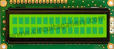
This type of LCD is widely used to display the status of the system and to display the obtain output. This LCD consists of 16 columns and 2 rows, therefore named as 16×2 LCD. Usually a LCD consists of two built in registers known as Data and Command register. Command reg is meant for giving commands such as blink on, cursor on/off etc while Data reg is to display the input character.

You have to follow these steps to write a command or data into the LCD.

  • Place the Data/Command in the pins D0-D7 of the LCD.
  • If you are intended to write command you gotta make the RS(register select) pin of the LCD low, that is RS=0
  • Whereas for writing data you have to make this RS high, that is RS=1
  • Then the EN of the LCD must undergo a high to low logic transition with some delay in between them, that is EN=1 to EN=0 with specific delay.
  • The R/W pin should remain in the Logic 0.

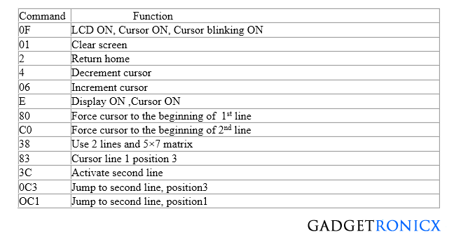
Usually LCD’s have some preassigned commands that would do specific tasks in functioning of the LCD. The command table of a 16×2 LCD is given below.


LCD-command-list-table-hex-values-data
Command Table for 16×2 LCD

Still not clear about the working of LCD? I suggest you to go through this Tutorial on LCD interface

4×3 Keypad:

We have used a 4×3 keypad which means it has four rows and three columns in it. The keypad was scanned for any key inputs and this was done by means of a method called polling. The scanning takes place by keeping a specific Row low at a time and read the status of the column pins as input at that instant. This chain goes on through all the rows and by this way input is read by Microcontroller.

Read how to constuct keypad and how the scanning works  in this Tutorial of Keypad Interface and scanning.


Rear More:  Interfacing LCD and Keypad with PIC16F877A Microcontroller

The post Interfacing LCD and Keypad with PIC16F877A Microcontroller appeared first on PIC Microcontroller.

7 Segment Display Interfacing with PIC Microcontroller

$
0
0

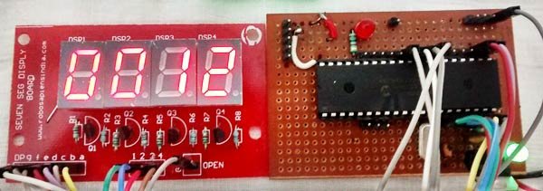
This is our 8th tutorial of Learning PIC microcontrollers using MPLAB and XC8. We have come up all the way from installing MPLABX to using a LCD with PIC MCU. If you are new here, then look at previous tutorials where you can learn timers, blinking LED, interfacing LCD etc.. You can find all our PIC Tutorials here. In our last tutorial we saw how we can generate Custom characters with our 16*2 LCD display, now let us equip our self with another type of display module called the 7-segment display and interface it with PIC Microcontroller.

7 Segment Display Interfacing with PIC Microcontroller

7 Segment Display Interfacing with PIC Microcontroller

Although 16×2 LCD is much more comfortable than 7-segment display but there are few scenarios where a 7-segment display would come in handier than a LCD display. LCD suffers from the drawback of having low character size and will be overkill for your project if you are just planning to display some numeric values. 7-segments also have the advantage against poor lighting condition and can be viewed from lager angles than a normal LCD screen. So, let us start knowing it.

7-Segment and 4-Digit 7-Segment Display Module:

7 Segment Display has seven segments in it and each segment has one LED inside it to display the numbers by lighting up the corresponding segments. Like if you want the 7-segment to display the number “5” then you need to glow segment a,f,g,c, and d by making their corresponding pins high. There are two types of 7-segment displays: Common Cathode and Common Anode, here we are using Common Cathode seven segment display. Learn more about 7 segment display here.

Now we know how to display our desired numeric character on a single 7-segment display. But, it is pretty evident that we would need more than one 7-segment display to convey any information that is more than one digit. So, in this tutorial we will be using a 4-digit 7-Segment Display Module

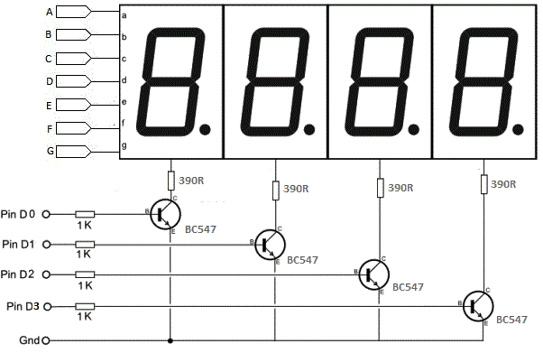
As we can see there are Four Seven Segment Displays connected together. We know that each 7-segment module will have 10 pins and for 4 seven segment displays there would be 40 pins in total and it would be hectic for anyone to solder them on a dot board, so I would highly recommend anyone to buy a module or make your own PCB for using a 4-digit 7-segment display. The connection schematic for the same is shown below:Schematic 7 Segment Display Interfacing with PIC Microcontroller

To understand how 4-digit seven segment module works we have to look into the above schematics, as shown the A pins of all four display is connected to gather as one A and the same for B,C…. upto DP. So, basically if trigger A on, then all four A’s should go high right?

But, that does not happen. We have additional four pins from D0 to D3 (D0, D1, D2 and D3) which can be used to control which display out of the four should go high. For example: If I need my output to be present only on the second display then only D1 should be made high while keeping other pins (D0, D2, and D3) as low. Simply we can select which display has to go active using the pins from D0 to D3 and what character to be display using the pins from A to DP.

For more detail: 7 Segment Display Interfacing with PIC Microcontroller

The post 7 Segment Display Interfacing with PIC Microcontroller appeared first on PIC Microcontroller.

LCD interface with Microcontroller PIC: Beginner’s guide using pic microcontoller

$
0
0

How to interface LCD (Liquid Crystal Display) display module to PIC microcontroller? LCD is a passive component, that is it does not make any light but just modifies the light passing through it for alphanumeric displays. LCD is exclusively manufactured to be used with microcontrollers, which means that it cannot be triggered by usual IC circuits. This embedded program shows how to connect PIC to LCD display module with microcontroller programming.Here 16×2 LCD interfaces with the PIC microcontroller. This type of LCD screen can display 2 lines with 16 characters each. Every character consists of 5×8 or 5×11 dot matrix. It can display all the letters of alphabet, Greek alphabet, mathematical symbols, punctuation marks etc. It is also likely to display symbols prepared by the user. Other positive features consist of automatic message shift (left and right), cursor appearance, LED back light etc. Interfacing LCD to microcontroller is quite simple program for beginners and easy to understand.

LCD interface with Microcontroller PIC Beginner’s guideEN – Enable:
This control line is used to inform the LCD that you are sending in data. To send data to the LCD, put data on the data bus, then make EN high (1) and wait a little bit and end by bringing EN to low (0) again.

RS – Register Select:
When RS is low (0), the information in the DB0 to DB7 pins are to be considered as an instruction (command- such as Clear screen, Display set, etc.). When RS is high (1), the information in the DB0 to DB7 pins are to be considered valid text data to print on the LCD screen. For example, to display the letter “i” on the screen you should set RS= high.

RW – Read/Write:
When RW is low (0), the information on the data bus is written to the LCD module.

DB0 to DB7:
Data bus lines of LCD display.

LED+, LED-:
Used for enabling back light on the screen. If you don’t want the back light you can leave it unconnected.

Basic connection circuit diagram of LCD interfacing with PIC

  • We can interface LCD to PIC in 4 bit mode
  • So D0, D1, D2, D3 of LCD display are grounded since connection is 4 bit mode and the D4, D5, D6, D7 are connected to Port C higher bits RC4, RC5, RC6, RC7 respectively.

LCD interface with Microcontroller PIC Beginner’s guide

  • RS pin of LCD module connected to RC2 (PORTC.F2), this will decide whether the LCD inputs are data input or instruction input. In the case of Mikro C compiler we doesn’t bother about this pin, only we need to initialize it as sbit LCD_RS at RC2_bit; rest all the operation done by LCD Library function inside Mikro C.
  • RW (Read/Write) pin grounded because we are writing to LCD display. (For writing RW=0; For reading RW=1;)
  • Enable (EN) pin connected to RC3 (PORTC.F3), a HIGH to LOW transition of this pin needed in order to transfer data or command from PIC to LCD module. As I said above, Mikro C LCD library function will do the job for us. Just initialize the bit as sbit LCD_EN at RC3_bit;


Fo more detail: LCD interface with Microcontroller PIC: Beginner’s guide

Current Project / Post can also be found using:

  • Serial LCD to pic micro

The post LCD interface with Microcontroller PIC: Beginner’s guide using pic microcontoller appeared first on PIC Microcontroller.

Display Custom Characters on 16×2 LCD using PIC Microcontroller and XC8

$
0
0

In our previous tutorial, we have learnt How to Interface a 16*2 LCD with PIC Microcontroller. We recommend you to go through it before going any further, if you are beginner in PIC microcontroller. Previously we have also learnt the basics of PIC using LED blinking Program and  Timers in PIC Microcontroller. You can check here all the tutorials on Learning PIC Microcontrollers using MPLABX and XC8 compiler.

display-custom-characters-on-16x2-LCD-using-pic-microcontroller

Display Custom Characters on 16×2 LCD using PIC Microcontroller

In this tutorial, let us make it more interesting by creating our own custom characters and displaying them on our LCD screen using PIC16F877A PIC Microcontroller. Also there are some pre-defined mostly used custom characters given by the HD44780A IC itself, we will also see how we can use them. As explained in our previous tutorial our LCD has a Hitachi HD44780 controller embedded on it which helps us to display characters. Each character that we display is already pre-defined inside the ROM of the HD44780 IC. We will learn about LCD controller IC HD44780, before displaying character on LCD.

16×2 Dot Matrix LCD Controller IC HD44780:

In order to display a custom character, we have to somehow tell the IC that how the custom character will look like. To do that we should know about the Three types of Memories present inside the HD44780 LCD controller IC:

Character Generator ROM (CGROM):  It is the read only memory which, as said earlier, contains all the patterns of the characters pre-defined inside it. This ROM will vary from each type of Interface IC, and some might have some pre-defined custom character with them.

Display Data RAM (DDRAM): This is a random access memory. Each time we display a character its pattern will be fetched from the CGROM and transferred to the DDRAM and then will be placed on the screen.  To put it simple, DDRAM will have the patterns of all characters that are currently being displayed on the LCD Screen. This way for each cycle the IC need not fetch data from CGROM, and helps in getting a short update frequency

Character generator RAM (CGRAM): This is also a Random access memory, so we can write and read data from it. As the name implies this memory will be the one which can used to generate the custom character. We have to form a pattern for the character and write it in the CGRAM, this pattern can be read and displayed on the Screen when required.

Now, since we got a basic understanding of the types of Memory present in the HD44780 interface IC. Let us take a look into its datasheet to understand a bit more.

As, the datasheet implies, the HD44780 IC has provided as 8 Locations to store our custom patterns in CGRAM, also on the right we can see that there are some pre-defined characters which can also be displayed on our LCD Screen. Let us see how we can do it.

Displaying a Custom Character on 16×2 LCD:

To display a custom character we must first generate a pattern for it and then save it to the CGRAM. Since we have the library functions with us already, it should be easy to do this with some simple commands. Here is the Library for LCD functions, but here we have copy-pasted all the Library functions in the program itself, so no need to include this header file in our program. Also check this article for Basic LCD working and its Pinouts.

The first step is to generate a pattern or the custom character. As we know each character is a combination of 5*8 dots. We have to select which dot (pixel) should go high and which should stay low. Simply draw a box like below and shade the regions based on your character. My character here is a stick man (hope it looks like one). Once shaded, simple write the equivalent binary value of each byte

Circuit Connections and Testing:

This project does not have any additional hardware requirement, we have simply used the same connections from the previous LCD interfacing tutorial and used the same board which we have created in LED blinking Tutorial. As always let’s simulate the program using Proteus to verify our output.Schematic Display Custom Characters on 16x2 LCD using PIC Microcontroller and XC8

For more detail: Display Custom Characters on 16×2 LCD using PIC Microcontroller and XC8

The post Display Custom Characters on 16×2 LCD using PIC Microcontroller and XC8 appeared first on PIC Microcontroller.

LCD Interfacing with PIC Microcontroller using MPLABX and XC8

$
0
0

This is our sixth tutorial in our PIC Tutorial Series, in this tutorial we learn Interfacing of 16×2 LCD with PIC Microcontroller. In our previous tutorials we have learnt the basics of PIC using some LED blinking Programs and have also learnt How to use Timers in PIC Microcontroller. You can check here all the tutorials on Learning PIC Microcontrollers using MPLABX and XC8 compiler.

LCD Interfacing with PIC Microcontroller using MPLABX and XC8

LCD Interfacing with PIC Microcontroller using MPLABX and XC8

This tutorial will be an interesting one because we will learn How to Interface 16×2 LCD with PIC16F877A, check the detailed Video at the end this tutorial. Gone are the old days where we used LEDs for user indications. Let us see how we can make our projects look more cool and useful by using LCD displays. Also check our previous articles on Interfacing LCD with 8051, with Arduino, with Raspberry Pi, with AVR.

Functions for Interfacing LCD with PIC Microcontroller:

To make things easier we have made a small library that could make things easy while using this LCD with our PIC16F877A. The header file “MyLCD.h” is given here for download, which contains all the necessary function to drive the LCD using PIC MCU. Library code is well explained by comment lines but if you still have doubts reach us through the comment section. Also check this article for Basic LCD working and its Pinouts.

Note: It is always recommended to know what is actually happening inside your header file because it will help you in debugging or while changing the MCU.

Now, there are two ways to add this code into your program. You can either copy all the above lines of code in MyLCD.h and paste them before the void main(). Or you can download the header file using the link and add them to the header file of your project (#include ” MyLCD.h “;). This can be done by right clicking on the header file and selecting Add existing Item and browsing to this header file.

Here I have copied and pasted the header file code into my main C file. So if you are using our code, then you don’t need to download and add the header file into your program, just use the complete Code given at the end of this Tutorial. Also note that this library will only support PIC16F series PIC Microcontroller.

Here I am explaining each function inside our header file below:

void Lcd_Start(): This function should be the first function that has to be called to start working with our LCD. We should call this function only once to avoid lag in the program.

void Lcd_Start()
{
  Lcd_SetBit(0x00);
  for(int i=1065244; i<=0; i--)  NOP();  
  Lcd_Cmd(0x03);
    __delay_ms(5);
  Lcd_Cmd(0x03);
    __delay_ms(11);
  Lcd_Cmd(0x03); 
  Lcd_Cmd(0x02); //02H is used for Return home -> Clears the RAM and initializes the LCD
  Lcd_Cmd(0x02); //02H is used for Return home -> Clears the RAM and initializes the LCD
  Lcd_Cmd(0x08); //Select Row 1
  Lcd_Cmd(0x00); //Clear Row 1 Display
  Lcd_Cmd(0x0C); //Select Row 2
  Lcd_Cmd(0x00); //Clear Row 2 Display
  Lcd_Cmd(0x06);
}

Lcd_Clear(): This function clears the LCD screen and can be used inside loops to clear the appearance of previous data.

Lcd_Clear()
{
    Lcd_Cmd(0); //Clear the LCD
    Lcd_Cmd(1); //Move the cursor to first position
}

void Lcd_Set_Cursor(x pos, y pos): Once started, our LCD is ready to take commands, we can instruct the LCD to set its cursor in you preferred location by using this function.  Suppose if, we need out cursor at 5th character of 1st row. Then the function will be void Lcd_Set_Cursor(1, 5)

void Lcd_Set_Cursor(char a, char b)
{
    char temp,z,y;
    if(a== 1)
    {
      temp = 0x80 + b - 1; //80H is used to move the cursor
        z = temp>>4; //Lower 8-bits
        y = temp & 0x0F; //Upper 8-bits
        Lcd_Cmd(z); //Set Row
        Lcd_Cmd(y); //Set Column
    }
    else if(a== 2)
    {
        temp = 0xC0 + b - 1;
        z = temp>>4; //Lower 8-bits
        y = temp & 0x0F; //Upper 8-bits
        Lcd_Cmd(z); //Set Row
        Lcd_Cmd(y); //Set Column
    }
}

void Lcd_Print_Char(char data)  : Once the cursor is set we can write a character to its position by simple calling this function.

void Lcd_Print_Char(char data)  //Send 8-bits through 4-bit mode
{
   char Lower_Nibble,Upper_Nibble;
   Lower_Nibble = data&0x0F;
   Upper_Nibble = data&0xF0;
   RS = 1;             // => RS = 1
   Lcd_SetBit(Upper_Nibble>>4);             //Send upper half by shifting by 4
   EN = 1;
   for(int i=2130483; i<=0; i--)  NOP(); 
   EN = 0;
   Lcd_SetBit(Lower_Nibble); //Send Lower half
   EN = 1;
   for(int i=2130483; i<=0; i--)  NOP();
   EN = 0;
}

void Lcd_Print_String(char *a): If a group of characters is to be displayed, then the string function can be used.

void Lcd_Print_String(char *a)
{
    int i;
    for(i=0;a[i]!='\0';i++)
       Lcd_Print_Char(a[i]);  //Split the string using pointers and call the Char function 
}

Each time the Lcd_Print_Char(char data)  is called, its respective character values is sent to the data-lines of the LCD. These characters reach the HD44780U in form of bits. Now this IC relates the bits to the character to be displayed by using its ROM memory as shown the below table. You can find bits for all the characters in the datasheet of HD44780U LCD Controller.

Circuit Diagram and Testing:

Below is the circuit diagram for Interfacing 16×2 LCD with PIC Microcontroller.Schematic LCD Interfacing with PIC Microcontroller using MPLABX and XC8

For more detail: LCD Interfacing with PIC Microcontroller using MPLABX and XC8

The post LCD Interfacing with PIC Microcontroller using MPLABX and XC8 appeared first on PIC Microcontroller.
Custom Characters on LCD using PIC – MPLAB XC8

$
0
0

I hope that you already go through our tutorial, Interfacing LCD with PIC Microcontroller – MPLAB XC8. HD44780 compatible controllers used in these LCDs allows us to define 8 custom characters in addition to the standard pre-programmed characters. In this tutorial we will learn, how to create custom characters on LCD using PIC Microcontroller and MPLAB XC8 compiler.Custom Characters on LCD using PIC – MPLAB XC8

DDRAM, CGROM and CGRAM

CGROM – Character Generator ROM

This is the memory which holds 5×8 or 5×10 dot patterns of predefined characters in the LCD. It can generate 208 5×8 dot character patterns and 32 5×10 dot character patterns.

DDRAM – Display Data RAM

This is the memory which holds the character data which is currently displayed on the LCD screen. Its capacity is 80×8 bits, ie 80 characters.

CGRAM – Character Generator RAM

This memory works similar to CGROM but as this is a RAM we can modify its data any time. So we can store our custom character patterns in this memory through program. We can store up to eight 5×8 character dot patterns or four 5×10 character dot patterns in this memory.


Character Generation

Characters are displayed on the LCD using 5×8 or 5×10 dot matrix. Most of the commonly available displays uses 5×8 dot matrix. We can simply create a custom character by defining each pixel in the dot matrix. Here is an example of creating Ω symbol on 5×8 dot matrix.Project List – 871 PIC Microcontroller Schematic Custom Characters on LCD using PIC – MPLAB XC8

For more detail: Custom Characters on LCD using PIC – MPLAB XC8

The post Custom Characters on LCD using PIC – MPLAB XC8 appeared first on PIC Microcontroller.
Interfacing LCD with PIC Microcontroller – Hi Tech C

$
0
0

16×2 Character LCD is a very basic LCD module which is commonly used in electronics projects and products. It contains 2 rows that can display 16 characters. Each character is displayed using 5×8 or 5×10 dot matrix. It can be easily interfaced with a microcontroller. In this tutorial we will see how to write data to an LCD with PIC Microcontroller using Hi-Tech C Compiler. Hi-Tech C has no built in LCD libraries so we require the hardware knowledge of LCD to control it. Commonly used LCD Displays uses HD44780 compliant controllers.Interfacing LCD with PIC Microcontroller – Hi Tech C

This is the pin diagram of a 16×2 Character LCD display. As in all devices it also has two inputs to give power Vcc and GND. Voltage at VEE determines the Contrast of the display. A 10K potentiometer whose fixed ends are connected to Vcc, GND and variable end is connected to VEE can be used to adjust contrast. A microcontroller needs to send two informations to operate this LCD module, Data and Commands. Data represents the ASCII value (8 bits) of the character to be displayed and Command determines the other operations of LCD such as position to be displayed. Data and Commands are send through the same data lines, which are multiplexed using the RS (Register Select) input of LCD. When it is HIGH, LCD takes it as data to be displayed and when it is LOW, LCD takes it as a command. Data Strobe is given using E (Enable) input of the LCD. When the E (Enable) is HIGH, LCD takes it as valid data or command. The input signal R/W (Read or Write) determines whether data is written to or read from the LCD. In normal cases we need only writing hence it is tied to GROUND in circuits shown below.

The interface between this LCD and Microcontroller can be 8 bit or 4 bit and the difference between them is in how the data or commands are send to LCD. In the 8 bit mode, 8 bit data and commands are send through the data lines DB0 – DB7 and data strobe is given through E input of the LCD. But 4 bit mode uses only 4 data lines. In this 8 bit data and commands are splitted into 2 parts (4 bits each) and are sent sequentially through data lines DB4 – DB7 with its own data strobe through E input. The idea of 4 bit communication is introduced to save pins of a microcontroller. You may think that 4 bit mode will be slower than 8 bit. But the speed difference is only minimal. As LCDs are slow speed devices, the tiny speed difference between these modes is not significant. Just remember that microcontroller is operating at high speed in the range of MHz and we are viewing LCD with our eyes. Due to Persistence of Vision of our eyes we will not even feel the speed difference.

Hope that you got rough idea about how this LCD Module works. Actually you need to read the datasheet of HD44780 LCD driver used in this LCD Module to write a Hi-Tech C program for PIC. But we solved this problem by creating a header file lcd.h which includes all the commonly used functions. Just include it and enjoy.


Functions in lcd.h

Lcd8_Init() & Lcd4_Init() : These functions will initialize the LCD Module connected to the following defined pins in 8 bit and 4 bit mode respectively.

8 Bit Mode :

#define RS RB6
#define EN RB7
#define D0 RC0
#define D1 RC1
#define D2 RC2
#define D3 RC3
#define D4 RC4
#define D5 RC5
#define D6 RC6
#define D7 RC7

4 Bit Mode :

#define RS RB2
#define EN RB3
#define D4 RB4
#define D5 RB5
#define D6 RB6
#define D7 RB7

These connections must be defined for the working of LCD library.

Lcd8_Clear() & Lcd4_Clear() : Calling these functions will clear the LCD Display when interfaced in 8 Bit and 4 Bit mode respectively.

Lcd8_Set_Cursor() & Lcd4_Set_Cursor() : These functions set the row and column of the cursor on the LCD Screen. By using this we can change the position of the character being displayed by the following functions.

Lcd8_Write_Char() & Lcd4_Write_Char() : These functions will write a character to the LCD Screen when interfaced through 8 Bit and 4 Bit mode respectively.

Lcd8_Write_String() & Lcd4_Write_String() : These functions are used to write strings to the LCD Screen.

Lcd8_Shift_Left() & Lcd4_Shift_Left() : These functions are used to shift the content on the LCD Display left without changing the data in the display RAM.

Lcd8_Shift_Right() & Lcd4_Shift_Right() : Similar to above functions, these are used to shift the content on the LCD Display right without changing the data in the display RAM.

8 Bit Mode

Circuit DiagramSchematic Interfacing LCD with PIC Microcontroller – Hi Tech C

For more detail: Interfacing LCD with PIC Microcontroller – Hi Tech C 

The post Interfacing LCD with PIC Microcontroller – Hi Tech C appeared first on PIC Microcontroller.
Interfacing LCD with PIC Microcontroller – MPLAB XC8

$
0
0

In this tutorial we will see How to Interface a 16×2 character LCD module with PIC 16F877A Microcontroller using MPLAB X IDE and MPLAB XC8 C Compiler. 16×2 Character LCD is a very basic and low cost LCD module which is commonly used in electronic products and projects. 16×2 means it contains 2 rows that can display 16 characters. Its other variants such as 16×1 and 16×4 are also available in the market. In these displays, each character is displayed using 5×8 or 5×10 dot matrix.Interfacing LCD with PIC Microcontroller – MPLAB XC8

For controlling LCD using MPLAB XC8 compiler we need to know the hardware of LCD. These LCDs commonly uses HD44780 compliant controllers. So we need to learn HD44780 Dot Matrix LCD Controller’s Datasheet. Don’t worry we already developed an LCD library including commonly used functions, so you can use it without any hardware knowledge of LCD.

First two pins GND and VCC (VSS and VDD) are for providing power to LCD display. 3ed pin VEE is used to control the contrast of the LCD display. A 10KΩ preset whose fixed ends connected to VDD, VSS and variable end connected to VEE can be used to control contrast of the LCD. A microcontroller or microprocessor need to send 2 types of information for operating this LCD Module, Data Information and Command Information. Data Information is the ASCII value of the characters to be displayed in the LCD screen and Command Information determines other operations such as position to be displayed, clear screen, shift etc. Data and Command Information are send to LCD through same data lines (DB0 – DB7) which are multiplexed using RS (Register Select) pin of LCD. When RS is HIGH LCD treats DB0 – DB7 data pins information as Data to be displayed and when it is LOW LCD treats it as Command Information. Enable (E) input of the LCD is used to give Data Strobe. HIGH (5V) Voltage Level in the Enable (E) pin tells the LCD that DB0 – DB7 contains valid information. The input signal R/W (Read or Write) determines whether data is written to or read from the LCD. In normal cases we need only writing hence it is tied to GROUND in circuit shown below.

The interface between this LCD and Microcontroller can be 8 bit or 4 bit and the difference between them is in how the data or commands are send to LCD. In the 8 bit mode, 8 bit data and commands are send through the data lines DB0 – DB7 and data strobe is given through E input of the LCD. But 4 bit mode uses only 4 data lines. In this 8 bit data and commands are splitted into 2 parts (4 bits each) and are sent sequentially through data lines DB4 – DB7 with its own data strobe through E input. The idea of 4 bit communication is introduced to save pins of a microcontroller. You may think that 4 bit mode will be slower than 8 bit. But the speed difference is only minimal. As LCDs are slow speed devices, the tiny speed difference between these modes is not significant. Just remember that microcontroller is operating at high speed in the range of MHz and we are viewing LCD with our eyes. Due to Persistence of Vision of our eyes we will not even feel the speed difference.


Hope that you got rough idea about how this LCD Module works. Actually you need to read the datasheet of HD44780 LCD driver used in this LCD Module to write a MPLAB XC8 program for PIC. But we solved this problem by creating a header file lcd.h which includes all the commonly used functions using 4 bit mode. Just include it and enjoy.

Circuit DiagramSchematic Interfacing LCD with PIC Microcontroller – MPLAB XC8

For more detail: Interfacing LCD with PIC Microcontroller – MPLAB XC8

The post Interfacing LCD with PIC Microcontroller – MPLAB XC8 appeared first on PIC Microcontroller.

Displaying Scrolling(Moving) text on 16×2 lcd Using Pic16f877 and Pic18f452 Microcontroller

$
0
0
Displaying moving or scrolling text on lcd(16×2,8×1,16×4,8×2,16×1,20×1,20×2 etc) is very easy. You just need to know how to efficiently use lcd commands.In this project i am using pic 16f877 microcontroller to display text and then scroll it on the lcd. The lcd which i am using is 16×2. Where 16 represents number of coulombs and 2 represents number of rows. The text which i am scrolling on the lcd is my website name “microcontroller-project.com”. The code is written in c language using mplab-ide with high tech c compiler.

Project requirements are

  • Pic 16f877 microcontroller
  • 16×2 lcd (I am using.)
  • Potentiometer (To set lcd contrast)
  • crystal(20MHz)
  • Power supply

If you are newbee and dont know much about 16×2 lcd working and pin out just go through this  simple tutorial. It will explain you about all the pins and functions of 16×2 lcd.

  1. 16×2 lcd pinout and working.

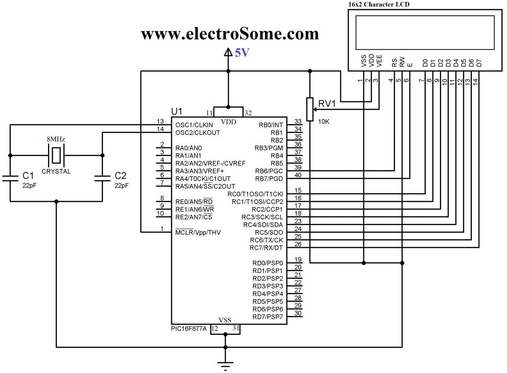
The circuit of the project is given below. Data pins of 16×2 lcd are directly connected to Port-b of microcontroller.The rd(read-write) pin of lcd is connected to port-d pin no 5. The rs(register select) pin of 16×2 lcd is connected to port-d pin 6.The en(enable)pin of 16×2 lcd is connected to port-d pin 7 of pic 16f877. 20MHz crystal is connected to pin 13 and 14 in parallel to two 33pf capacitors. Apply 5volts to pin 1,11&32. Ground pin 12 and 31. Set lcd contrast using potentiometer.

Schematic Displaying Scrolling(Moving) text on 16x2 lcd Using Pic16f877 and Pic18f452 Microcontroller

Scrolling text on lcd – circuit diagram

The code is written in c language and is easy to understand and to modify. First include the necessary header file #include<htc.h>. This header file is necessary to be included if you are using high tech c compiler. Then #define _XTAL_FREQ 20000000 is defining our crystal frequency which is 20MHz. This crystal frequency is necessary to be defined if you are using __delay_ms() & __delay_us() predefined functions. These predefined functions are used to generate delay in ms() milli seconds and us() microseconds. I made my own delay function so i am not using thesepredefined functions. Than a character array is inialized. The array size is variable. It contains my website name “microcontroller-project.com”. This is the text which i want to scroll on my lcd.

After the header files now its time to define our functions. First i defined delay function it is used to generate some delay in program execution.Then lcdcmd() function is sending commands to 16×2 lcd. For sending commands first put your command on port-b then select register(for command register make rs=0) then select which operation you want to perform read or write(for read rw=1 and write rw=0) now give strobe to write command present on data pins of lcd to lcd controller, make en high(en=1) and low (en=0) with some delay for this purpose. display() functions works in the same way as lcdcmd but with little difference that except command it is writting data on lcd and you just need to select the data register to write data(rs=1 takes you to lcd data register).

lcdint() function is intializing our lcd and ports.TRISB=0x00 declares port-b as output port.TRISD5=0,TRISD6=0 & TRISD7=0 are making individual pins of port-d as output. Rest of the commands are initializing our 16×2 lcd. If you want to know about the funtions of the commands just go through the tutorial(Link is given at the top after first paragraph).

In the main function i am displaying text on lcd. I start displaying text from first coulomb of row 1 and when my text reaches at the end of the row 1 i start scrolling the text to the left.The statement if(i>=14){lcdcmd(0x18);} is performing this function. When my text reaches to last coulomb of 16×2 lcd which is 15 i start scrolling it to left. The command 0x18–>lcdcmd(0x18) scrolls the text.

I recommend you to please go through the tutorial 16×2 lcd pinout and working if you dont understand commands and their working.

For more detail: Displaying Scrolling(Moving) text on 16×2 lcd Using Pic16f877 and Pic18f452 Microcontroller

The post Displaying Scrolling(Moving) text on 16×2 lcd Using Pic16f877 and Pic18f452 Microcontroller appeared first on PIC Microcontroller.
Message Pump using PIC16F687 microcontroller

$
0
0

Brief:

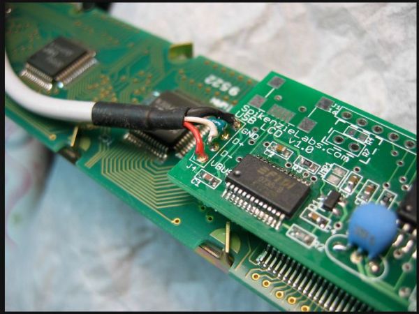
The Message Pump A.K.A. the USB to LCD Backpack is a device that allows you to connect a LCD display directly to your computer. It uses a PIC micro-controller, to drive the LCD and a FTDI USB to serial chip to connect to your computer.

The great thing about the FTDI chip is that it’s drivers are available for Macintosh, Windows, and Linux! The FTDI chip works by creating a VCP (virtual com port) and you may already have these drivers on your computer if you use an Ardunio Diecimila. If not, no worries they are free and and easy install.

What does it do?

Once a VCP is opened to the Message Pump any ASCII serial data sent to it is displayed on the LCD display.

This means that if you have software on your computer that can access a serial port you can display messages on the Message Pump!

The possibilities are endless, imagine using AppleScript, Processing, Basic or whatever your preferred programming / scripting language is, you could display messages like;

Message Pump

  1. BulletHow many e-mails you have
  2. BulletThe current date and time
  3. BulletCPU temperature
  4. BulletRSS feeds
  5. BulletHits on your web page
  6. Bullet ….

How to use it-Basics:

The easiest way to use the Message Pump is to open Hyper-terminal or an other terminal software, select and open the COM port for the Message Pump, then just start typing. What you type is displayed directly onto the LCD display. If you are using other software you will have to check how to open a serial port in that software.

To get you started I’ve made a simple Processing example. It is called MessagePumpDemo.pde and uses the Serial Library included with Processing.

The way MessagePumpDemo works; first it lets you select a serial port, then it opens that port at the default baud rate of 9600 bps and prints pumps out a message. It also lets you send keystrokes to the display. It’s a building block for you to examine and make better.


How to use it-Advanced:

The Message Pump also accepts instructions to control settings and formatting. These are used to change things such as the size of display, for example 1×16 to a 4×20 character display, baud rate etc. You can also jump to a specific space on the display. The instructions also include the ability to pass though, Hitachi commands right into the display. For example; clear display, shift left etc.


An instruction is always three bytes long and it always starts with the hex value of 0x80. The next value is the instruction and the third is the value of the instruction.


For more detail: Message Pump using PIC16F687 microcontroller

Current Project / Post can also be found using:

  • circuit of scrolling lcd with p ic and source code

The post Message Pump using PIC16F687 microcontroller appeared first on PIC Microcontroller.
Build a PIC controlled DDS VFO, 0 to 6 MHz using pic microcontroller

$
0
0

Files contained in MINIDDS.ZIP:

  readme.txt      Read this first!
  compplac.pdf    Component placement in PDF format
  schema.pdf      Schematic diagram in PDF format
  top.ps          PCB top copper layer in Postscript format
  bottom.ps       PCB bottom copper layer in Postscript format
  ad9832_4.asm    PIC assembly source code
  p16f84.inc      Needed for assembly of ad9832_4.asm (for 'F84)
  p16c84.inc      As above but for 'C84
  vfo5x7f.hex     PIC16F84 program for LCD with 5x7 font
  vfo5x10f.hex    PIC16F84 program for LCD with 5x10 font
  vfo5x7c.hex     PIC16C84 program for LCD with 5x7 font
  vfo5x10c.hex    PIC16C84 program for LCD with 5x10 font
  filtresp.pcx    Computed frequency response of lowpass filter

Build a PIC controlled DDS VFO, 0 to 6 MHzDownload MINIDDS.ZIP (186K)

Download MINIDDS.PDF (209K)

If you prefer to control the DDS module from a PC (instead of using a PIC), try this:

Download PCVFO.ZIP (18K)

The zip archive contains a single file, VFO.EXE. It is a DOS program but it runs fine in a Windows 95/98 “DOS bubble” as well (see screenshots above).

Are you looking for a DDS based 136 kHz longwave transmitter exciter?

Have a look at G0MRF’s page

Specifications:

  • Start-up frequency: 137.00000 kHz
  • Tuning range: 135.70000 to 137.80000 kHz in 0.25 Hz steps
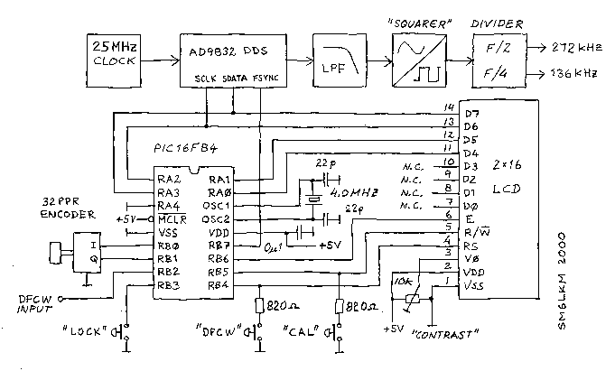
  • DFCW offset: 0 to 50 Hz adjustable in 0.25 Hz steps
  • The dial can be locked to prevent inadvertent QSY
  • Calibration: +/- 200 ppm, stored in EEPROM.
  • Actual DDS output frequency is 4 * dial frequency

Schematic and source code for the PIC controller is available here:

Download the PIC program lwex.zip

The PIC program is written for the free version of the CC5X C compiler which is available at www.bknd.com
Build a PIC controlled DDS VFO, 0 to 6 MHzAlmost any 2×16 character LCD module with Hitachi HD44780 controller chip will work. The LCD pin numbers on the schematic are not valid for all LCD modules. Please check the actual signal names on your particular LCD module.
The selected DFCW frequency offset will be added to the output frequency when the DFCW input is grounded. This input has a weak pull-up in the PIC.

The encoder inputs also have internal pull-ups in the PIC.

The switches “LOCK”, “DFCW” and “CAL” are momentary pushbuttons.


For more detail: Build a PIC controlled DDS VFO, 0 to 6 MHz

The post Build a PIC controlled DDS VFO, 0 to 6 MHz using pic microcontroller appeared first on PIC Microcontroller.
PIC32 Multimedia Expansion Board Review Video

$
0
0

Review of the Multimedia Expansion Board for the PIC32 Start Kits from Microchip.
In this review I’m going to show the board and it’s periphirals, and then I will show a couple of demostration applications.

Current Project / Post can also be found using:

  • lcd 8×2 proteus

The post PIC32 Multimedia Expansion Board Review Video appeared first on PIC Microcontroller.

A new multi-function power supply unit for my Embedded Lab

$
0
0

One important parameter in embedded system designing is power consumption. This parameter is directly related to the battery lifetime, if the system is to be powered from a battery. In order to determine the power rating of your designed system, you need to know how much current the system draws from the source at a given voltage. While working on my projects, I usually measure current by placing an external ammeter in series with the current’s return path. This is not always convenient to do, and so I thought of making a special power supply unit for my lab that would display both voltage and current information on a LCD screen while prototyping my circuit. This way I can continuously monitor how much power my test circuit is drawing at a specific operating voltage.

A new multi-function power supply unit for my Embedded Lab

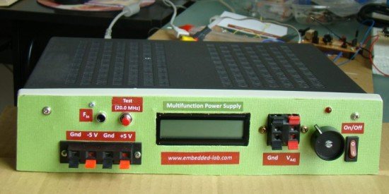
Multifunction bench power supply

This power supply unit provides fixed ±5 V as well as a variable dc voltage ranging from 1.25 V to  9 V. A PIC16F689 microcontroller is embedded into the power supply unit to measure the adjustable output voltage along with the load current. Besides, this unit also has a built-in frequency counter to measure the frequency of an external signal. The range is over 50 MHz. However, it has been tested up to 20.0 MHz, and works fine. There are still few I/O ports of PIC16F689 that are not used. So I am thinking about adding one or more features (like capacitance meter) to it. But that would be on my second version.

Theory

The fixed ±5 V power supplies are derived using LM7805 and LM7905 regulator ICs. A 12 V rectified output from a center-tapped transformer provides the dc inputs to these regulator ICs. For the variable dc output, a LM350 IC is used. LM350 is an adjustable 3-terminal positive voltage regulator that is capable of supplying in excess of 3A over a 1.2V to 33V output range. It requires only 2 external resistors to set the output voltage. Since my dc input is only 12 V (rectified output from the transformer), the regulated output from the LM350 IC would go up to 9 V (3 V less than the input, as specified in the datasheet). In order to obtain the full range of output voltage (up to 33 V) from LM350, you need a transformer with a higher output voltage. I rarely use power supply above 5 V in my projects, and therefore, a variable voltage source up to 9 V is good enough for me.

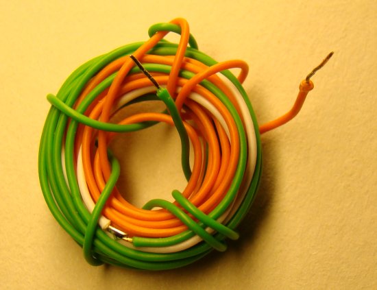
Next comes PIC16F689 microcontroller that measures the LM350 output voltage and current. You are right, I am implementing voltage and current measurement only to the LM350 output. The principles of voltage and current measurements using microcontroller were discussed in two of my posts: PIC-based digital voltmeter and How to measure dc current with a microcontroller. I am not going to repeat the details here. Both the parameters can be measured with built-in ADC channels of PIC16F689. Since the output voltage from LM350 could go higher than 5 V (up to 9 V in this situation), it is not directly  measurable from an ADC channel. A simple voltage divider network using two resistors is incorporated to scale down the output voltage to the safe ADC input range (0-5 V). On the other hand, the current to be measured must be first converted into voltage so that it could me measureable too with the ADC channels. The current to voltage conversion can be done by placing a small value resistance (shunt) in series with the current path. The voltage drop across the resistance will then vary linearly with the current. I am using a 0.286 ? resistor (Rs) made by myself by coiling a 5 ft long 22 AWG solid copper wire that has a plastic insulation on its outer surface (see the picture below).

Resistor A new multi-function power supply unit for my Embedded Lab

Current sensing resistor

Since this resistance is so small in value, the voltage drop across won’t be very high for small currents. Even for 1 A of current, the voltage drop across it would be only 0.286 V. To improve the resolution (and hence accuracy) of current measurement, this voltage must be amplified before the AD conversion process. An operational amplifier with a suitable gain can do this task. The figure below shows how this whole technique works.

For more detail: A new multi-function power supply unit for my Embedded Lab

Current Project / Post can also be found using:

  • lcd project for beginners with pic 16f family

The post A new multi-function power supply unit for my Embedded Lab appeared first on PIC Microcontroller.
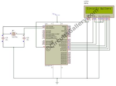
How to interface 16×2 LCD in 4-bit mode with PIC18F4550

$
0
0

The 16×2 character LCD can work in two modes, namely, 8-bit and 4-bit. These modes basically correspond to the number of data pins used in interfacing LCD. 8-bit mode uses all the data lines and has been explained in LCD interfacing with PIC18F4550. In 4-bit mode, only four data pins of LCD are connected to the controller. This mode, thus, saves four pins of the controller unlike 8-bit mode. The configuration and display method of LCD in 4-bit mode has been explained here.

interface 16x2 LCD

The 8-bit mode of LCD interfacing with PIC has been explained earlier. In the 4-bit mode the (8-bit) data/command is sent in nibble (four bits) format to LCD. The higher nibble is sent first followed by the lower nibble. In 4-bit mode only four data pins (D4-D7) of LCD are connected to the controller. The control pins (RS, RW and EN) are connected the same way as in 8-bit mode. The connections of LCD with PIC18F4550 are shown in the adjoining circuit diagram. Please note that here only PortB is used to connect data lines as well as control lines unlike in 8-bit mode. Refer LCD interfacing with PIC in 8-bit mode.

LCD is configured for 4-bit mode by sending appropriate instruction known as Function Set. The Function Set is hexadecimal instruction for LCD MPU unit which selects the working modes of LCD. The Function Set is given below along with its description.
Instruction
RS
RW
D7
D6
D5
D4
D3
D2
D1
D0
Function Set
0
0
0
0
1
DL
N
F
Description: 
DL       –           Data Length
N         –           No. of Lines
F          –           Font
 Value
 DL
 N
F
1
8 bit
2 lines
5×10 dots
0
4 bit
1 line
5×7 dots
According to the table, the value of Function Set for 4–bit mode will be [ 0010 0000 ] 0x20. The value of Function Set for the LCD configuration : 2 line (N=1), 5×7 dots (F=0) and 4-bit (DL=0) mode will be [ 0010 1000 ] 0x28.
It is important to note that when the power supply is given to LCD, it remains in 8-bit mode. In this state if 0x20 is sent, lower nibble will not be received by LCD because only four data lines (D4-D7) are connected, so 0x02 is sent instead of 0x20.

Current Project / Post can also be found using:

  • pic18f452 lcd

The post How to interface 16×2 LCD in 4-bit mode with PIC18F4550 appeared first on PIC Microcontroller.
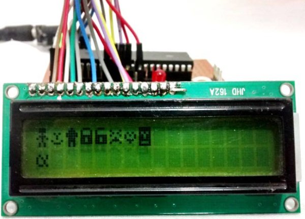
Interfacing 16×2 Lcd With 8051 Circuit Pin Diagrams

$
0
0

Microcontroller based electronic circuit diagrams, Electronic circuit diagrams / circuit schematics. if you would like general assistance with a specific design question you may like to try the electrical engineering.


Interfacing 16×2 Lcd With 8051 Circuit Pin Diagrams

Interfacing lcd modules pic microcontrollers., In this tutorial we will learn how we can use lcd modules with microchip pic microcontrollers. here i will present my lcd library which you can use to create lcd. Microchip, Mplab x ide with p18f87j60 and tcpip stack; interfacing current transformer with pic16f88; microstick sn visible but self test says ‘could not connect’.

Interfacing 16×2 Lcd With 8051 Circuit Pin Diagrams

Lcd tutorial interfacing microcontrollers, Lcd tutorial – hd44780 alphanumeric lcd interfacing tutorial microcontroller pic, 8051 avr. character based lcd hd44780 cgram ddram explaination . http://www.8051projects.net/lcd-interfacing/introduction.php Lcd tutorial interfacing microcontrollers, Lcd type hd44780 interfacing tutorial microcontroller pic, 8051 avr. character based lcd hd44780 cgram ddram explaination pinouts connection. http://www.8051projects.net/lcd-interfacing/ Hd44780 16×2 char lcd interfacing microcontroller, An alphanumeric cost lcd display essential small big projects display type information. hitachi hd44780 chipset based 16×2 char. http://www.circuitvalley.com/2011/09/hd44780-16×2-char-lcd-interfacing-with.html


For more detail: Interfacing 16×2 Lcd With 8051 Circuit Pin Diagrams

Current Project / Post can also be found using:

  • project on L C D

The post Interfacing 16×2 Lcd With 8051 Circuit Pin Diagrams appeared first on PIC Microcontroller.

2-wire LCD interface using PIC16CF84

$
0
0

Alphanumeric LCD displays have become very popular for microcontroller applications because they can add a lot to a project in a variety of different ways. A text message giving the user instructions as well as feedback can make the application seem much more “professional” and easy to use. I like to use LCD’s to help debug applications, with breakpoints set to display variable and I/O conditions and they are a lot cheaper than using a microcontroller emulator. To top it off, surplus LCD’s can be found for a dollar or less.

The most popular LCD interface is the Hitachi 44780 based LCD controller chip which provides a fairly easy to work with interface and low power consumption. The major drawback of the interface is the perceived complexity of working with the interface. This perception has been promoted by the lack of good (i.e. well translated) and accurate datasheets and web site information.

2-wire LCD interface using PIC16CF84Often the biggest stumbling block to using alphanumeric LCD displays is the number of pins required to control them. For the Hitachi 44780, twelve pins are required from the microcontroller to interface to the display for it to work in eight bit mode. For many smaller microcontrollers, twelve pins are not available or will be better served in the application. To be fair, this can be reduced to six by using the 44780’s “Four Bit” mode, but this can still be more than acceptable for most applications.

A popular solution that only requires one pin from the microcontroller to the LCD is the use of “Serial LCD Interfaces”  to the data and signals necessary for the Hitachi 44780 controllers.

Many of these products (such as the SLI-OEM) are excellent and can provide useful product interface and debugging information. The only drawback to them is the need for properly timed NRZ serial data which may be difficult or even impossible to guarantee in some applications.

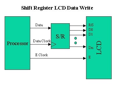
In this case, different approaches have to be made. The most popular one is to use synchronous serial data (requiring a “clock” and “data”) pin to load a serial-in/parallel-out shift register with the data bits and “R/S” pin information. The “E” Strobe Pin is driven directly by the microcontroller to latch in the data from the LCD.

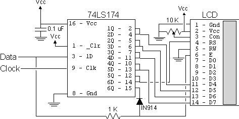
2-wire LCD interface using PIC16CF84 SchematicThe project presented in this article is an enhancement of this circuit. By combining the shift register’s “Data Line” with the most significant bit of the shift register, the “E” Strobe can be implemented without resorting to a separate line for the function. The 1 K resistor and diode act as an “AND” gate.

The operation of the resistor/diode “AND” gate may not be immediately obvious. When the shift register bit is low, the diode pulls the connection to the “E” pin low. When the shift register bit is high, the diode will not cause any current flow from the connection at the “E” pin to the shift register. The resistor from “Data” to the “E” pin is a current limiting resistor. When the shift register bit is low and the data bit is high, then the current through the resistor will be limited to 5 mA (for a 5 Volt logic application). At the “Data” side of the resistor, the voltage will still be high, even though the diode is pulling the “E” pin low.


For more detail: 2-wire LCD interface using PIC16CF84

Current Project / Post can also be found using:

  • MICROCHIP LCD projects

The post 2-wire LCD interface using PIC16CF84 appeared first on PIC Microcontroller.
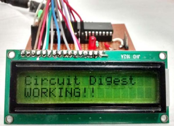
Traffic Message Channel receiver using PIC18F8722

$
0
0

Main roads traffic status and incident report and display.


Technical specifications:

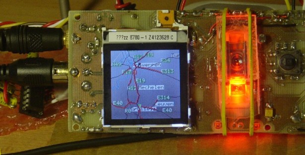
  • Dual display: colour road map (left) and detailed text messages (right) both with LED backlight.
  • Up to 120 TMC messages are stored in memory.
  • Auto/manual TMC message scrolling.
  • GPS position locator/follower optional.
  • Map navigation with  mouse sensor and/or micro joystick.
  • Map zoom 10km to 80km (in 10km steps)
  • City and area presets preconfigured.
  • High quality NXP TEF6901AH chip used for best performance.
  • Integrated RDS/RBDS radio data demodulator.
  • All parts will be available at our shop.

  • TMC countries to be supported: Belgium , Netherlands, Germany , France , Sweden  and more to come…
  • This product will be ported to a smaller OLED OmniBoard project (054 – LiveQ) and will be available as a KIT (PCB + parts) from our online shop.

Traffic Message Channel receiver

Free schematics and source code available for download. Last update: August 15, 2008.

Dual display, mouse touchpad and joystick.

Power in (9V..12V AC/DC)

The tuner TEF6901AH, microcontroller PIC18F8722, USB controller, Memory card and power supply  are located on the backside.

  • Audio output and antenna input.
  • Nokia 6610 Colour LCD (128×128) with road map.
  • Mouse sensor (red) for touchpad navigation.
  • Micro joystick for controls and navigation.


For more detail:  Traffic Message Channel receiver using PIC18F8722

Current Project / Post can also be found using:

  • door project with pic
  • car burglar alarm with pic 16f877a
  • pic project for dashcam

The post Traffic Message Channel receiver using PIC18F8722 appeared first on PIC Microcontroller.
Viewing all 253 articles
Browse latest View live


<script src="https://jsc.adskeeper.com/r/s/rssing.com.1596347.js" async> </script>