Quantcast
Channel: LCD Projects - PIC Microcontroller
Viewing all 253 articles
Browse latest View live

Displaying text on LCD by interfaced with PIC16F877 microcontroller in 4 bit mode

$
0
0

Here I discuss on very good and simple project on displaying text on LCD by interfaced with PIC16F877 microcontroller in 4 bit mode.to start with this project you need some Knowledge on how to start project on PIC micro controller I assumed you know that if not please you should visit my previous post

Step by step Project guide on PIC Microcontroller

Simple Project on LED blinking by PIC 16 Microcontroller

Now to start with displaying text on LCD by interfaced with PIC16F877 microcontroller in 4 bit mode, we need support of

  • 1 Proteus 7 Professional (where we Make your hardware arrangement our project and simulate it to see the result)
  • 2 Mikcro C. (here we write the Embedded C Program and build the hex file of that)

 Displaying text on LCD by interfaced with PIC16F877 microcontroller in 4 bit mode

So for making any microcontroller based program you need to build the hardware interfacing first then you can define your interfaced port in programming.

So we start with Proteus 7 Professional 

To build Displaying text on LCD by interfaced with PIC16F877 microcontroller in 4 bit mode, we need to add some device in proteus. Those are

  • 1)      Crystal
  • 2)      Pic16f877
  • 3)      LM016L ( LCD display)

Now how to add, make the interfacing and to see the result of our project how it simulates? see my video in below where I show you step by step.


Now in programing portion let see in MiKcro C see what we have to do?

Look from circuit in proteus we can see that we use Port D of PIC16F877 for interfacing with LM016L LCD display board. So we have to make Port d as out port and also we have to initialize port d for LCD. So we use some command to make our project those are

  •       TRIS                                     ( for defining Port as In/Out Port)
  •       LCD_init                              (for initializing port of microcontroller);
  •       LCD_CLEAR                         ( we use this for clear the lcd screen)
  •       LCD_CURSOR_OFF            (to off the cursor of lcd)
  •       LCD_out                              (To out data from micro controller to lcd)

For more detail: Displaying text on LCD by interfaced with PIC16F877 microcontroller in 4 bit mode

The post Displaying text on LCD by interfaced with PIC16F877 microcontroller in 4 bit mode appeared first on PIC Microcontroller.


Embedded Linux Controller using pic microcontoller

$
0
0
An In-Circuit Debugger (ICD) is a very powerful and effective tool for real-time debugging of a microcontroller-based system at hardware level. It allows you to run, halt and single step the program while the target microcontroller is embedded in the actual circuit. Once halted, the program variables, Special Function Registers (SFRs), RAM and EEPROM locations can be examined and modified in real-time, thus assists the designer in debugging the firmware and hardware together. In this article, I am going to describe the In-Circuit Debugging technique in PIC microcontrollers, and demonstrate the debugging procedure with a test project using the PIC16F887 microcontroller. Although the operation of most ICDs are similar, here I will be using mikroElektronika’s PICFlash with mikroICD device in conjunction with the mikroC Pro for PIC compiler for illustrative purpose.
Embedded Linux ControllerTheory

An ICD is a hardware device that is connected between a PC and the target microcontroller to debug real-time applications quickly and easily. The ICD is controlled by a debugging application tool running on the PC. The debugging tool allows the designer to slow down the microcontroller operation by inserting breakpoints into the program 0r single-step the program execution. After the execution of a single or a group of instructions, the values of the program variables and internal registers can be examined, and modified if required. This helps to quickly identify bugs and errors in the source code and thus expedite the development process of the project.

ICD in PICMicro

In PIC microcontrollers, in-circuit debugging is achieved through the same pins that are used for In-Circuit Serial Programming (ICSP), i.e. ICSPDAT (or PGD), ICSPCLK (or PGC), VPP/MCLR (programming mode voltage), VDD (power supply voltage), and VSS (Ground). This allows manufacturers to integrate ISCP programming and in-circuit debugging features into a single device. During debugging, the ICD device adds an additional block of code (along with the user application) to the target microcontroller’s program memory, which interacts with the debugging application and sends variable values, internal register values and other details to the PC through the same programming cable.

For example, Microchip’s MPLAB ICD2 and ICD3 are both programmer and real-time debugger for selected PIC MCUs and dsPIC DSCs. The functionality of the ICD is controlled by the MPLAB Integrated Development Environment (IDE) application software running on the PC. During debugging all available features of the target microcontroller are accessible interactively through the MPLAB IDE interface. These functions allow you to run the program in single-step mode, insert breakpoints into the program, examine the registers and variables, and modify them if desired.

Although an ICD is an invaluable debugging tool, it does not come at no cost. The two main disadvantages of ICD are: 1) it uses some memory of the target microcontroller, and 2) it occupies a few I/O pins of the target microcontroller to communicate with the PC. Therefore, while debugging, the PGD, PGC, and MCLR pins of the target microcontroller cannot be used for any other purposes.

PICFlash with mikroICD

The PICFlash with mikroICD is a programmer and in-circuit debugger for PIC12, PIC16, and PIC18 series microcontrollers. It is manufactured by mikroElektronika and is supported by all of its PIC compilers (mikroC, mikroBasic, and mikroPascal). The device communicates with PC through an USB interface, which also provides the necessary power for the ICD. ?It connects to the target PIC microcontroller through the PGC, PGD, VPP/MCLR and power supply pins. When this device is used as an standalone programmer, the first three pins are released after the HEX file is loaded into the target PIC microcontroller. But if  it is used for in-circuit debugging, those three pins are used for communicating with the PC and hence cannot be used for any other purposes.

Installing software for PICFlash with mikroICD

You can find the detail information about this in the mikroICD manual. The easiest way to setup this device is to download the PIC compiler first. Note that this device does not work with any other party’s compiler, so you need one of mikroElektronika compilers to make it work. The following steps describes the software installation and setup of PICFlash with mikroICD for mikroC Pro for PIC compiler.

  1. First, download mikroC Pro for PIC compiler from HERE and install it on your PC.
  2. When the installation is complete, it will ask if you want to install mikroProg Suite for PIC. Say yes, and install that too.
  3. Next, it will ask if you want to install the drivers for mikroProg programmer. Say yes, and select the driver file suitable to your operating system, and install it. You are done!

Embedded Linux ControllerUsing PICFlash with mikroICD for Debugging

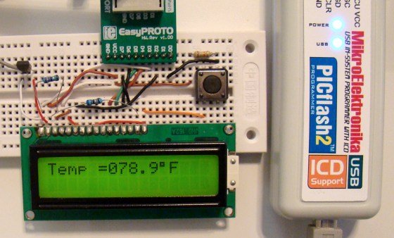
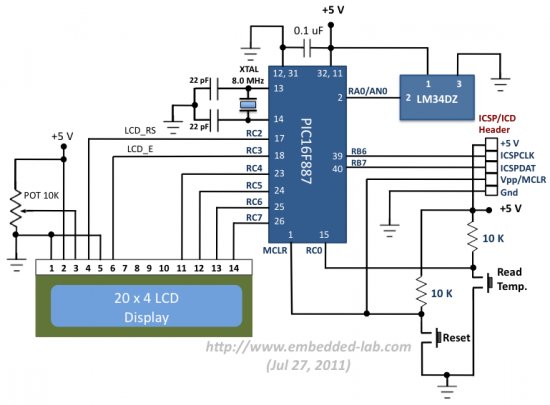
The first step of using the mikroICD is writing an application program in the chosen compiler, say mikroC Pro for PIC. The compiler’s IDE provides debugging functions such as running the program step by step, pausing the program execution using breakpoints, examining the state of the internal registers, tracking the values of variables in the program, etc. Please read the mikroICD manual for further detail. I will be illustrating the debugging procedure with our test project that uses PIC16F887 microcontroller and LM34DZ sensor to measure the ambient temperature and display it on LCD. The circuit diagram for this project is shown below and is self-explanatory. The way it works is every time the Read Temp. switch is pressed, the microcontroller reads the temperature sample from the LM34DZ and displays it on the LCD. You can see that under default condition, the switch output is High, and it goes Low when the switch is pressed. I am using mikroElektronika’s PIC Ready 1 board for this experimental setup. It is a quick prototyping board for 28 and 40 pin PIC microcontrollers. The board comes with a PIC16F887 microcontroller, preloaded with a serial bootloader, which is actually not applicable in our case. However, the board does contain connectors for PICFlash with mikroICD too. The user’s manual for PIC Ready 1 board describes more about the on-board connections.

For more detail: Embedded Linux Controller

The post Embedded Linux Controller using pic microcontoller appeared first on PIC Microcontroller.

PIC16F84A LCD interfacing code (using 3 pins only) + Proteus simulation

$
0
0

This post provides the LCD[1] interfacing code using only 3 pins of PIC16F84A microcontroller. This code is written in C language using MPLAB with HI-TECH C compiler. You can download this code from the ‘Downloads‘ section at the bottom of this page.

PIC16F84A LCD interfacing

It is assumed that you know how to make an LED blink with PIC16F84A microcontroller. If you don’t then please read this page first, before proceeding with this article.

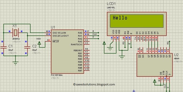
PIC16F84A microcontroller has 13 IO pins. A 4×4 keypad needs 8 pins to interface with controllers. LCD needs at least 6 pins to interface with controllers. In order to interface keypad and LCD, both with PIC16F84A we need at least 14 pins. So it is not possible to directly attach LCD and keypad both with PIC16F84A even in 4bit mode[2]. To make this possible, a serial to parallel shift register IC (4094) is used in this circuit. In this way by only using 3 pins of PIC16F84A microcontroller, we can interface LCD with it in 4bit mode. This is shown below in the figure.

In the above figure, RA0 pin is being used as Enable pin for LCD. RA1 pin is used as Clock pin and RA2 pin is used as Data pin for 4094 IC. When code starts running, then Hello is displayed on the LCD screen as shown in the above figure.

PIC16F84A LCD interfacing schematic

Code

In the code you can easily select pins to be used for interfacing with the LCD. Following figure shows the pin selection code.

Here for example, you can change RA0 to RA3 if you want to attach Enable pin of the LCD on pin2 of PIC16F84A. You will also need to change LCD_E_Dir to TRISA3 for RA3.

The code for the main function is shown below.

Downloads

LCD interfacing code using 3 pins for PIC16F84A was compiled in MPLAB v8.85 with HI-TECH C v9.83 compiler and simulation was made in Proteus v7.10. To download code and Proteus simulation click here.


For more detail: PIC16F84A LCD interfacing code (using 3 pins only) + Proteus simulation

The post PIC16F84A LCD interfacing code (using 3 pins only) + Proteus simulation appeared first on PIC Microcontroller.

How to choose a MicroController using PIC16C84 microcontroller

$
0
0

How to choose a MicroController

It used to be that the number of different microcontroller chips available to the hobbyist was pretty limited. You got to use whatever you could manage to buy from the mail-order chip dealer, and that narrowed down the choice to a small number of chips.

But times have changed. Digikey lists over 16000 different line items under a ‘microcontroller’ search. Which one should a hobbyist with no particular prior experience choose?

Here are some hints. These are particularly aimed at someone trying to pick a microcontroller to use for the first time at least partially as a learning experience, rather than someone who wants to accomplish a particular task.

Update 2009-01-28: This Instructable was recently mentioned in some popular blogs, and is getting a bunch of new readers. Be sure to read the ‘comments’ made by other readers and the responses to them; there’s a lot of value in those comments…

Step 1

What IS a “Microcontroller” ?

If you ever took a very introductory computer course, you probably learned about the major components of ANY computer:

    • A Central Processing Unit or CPU. The part that actually performs logic and math
    • Memory. Where the computer stores data and instructions
    • Input and Output or I/O. How the computer moves data between its other components and the real world.

A microprocessor uses microelectronic fabrication techniques to shrink the CPU to a very small size; usually a single “chip.”

A microcontroller uses the same techniques to shrink the entire computer to a single chip (or very small module.) CPU, Memory, and I/O all in a little package as small as a grain of rice. Just connect up power and it starts doing its thing; computing and talking to the world. Usually the I/O on a microcontroller is aimed at “low level” hardware like talking to individual switches and LEDs instead of keyboards, internets, and displays (like your desktop computer.) A microcontroller is just the thing you want, if you want to talk to individual switches and LEDs…

Step 2

Show Stoppers

There are a number design considerations that might immediately reduce your number of choices a great deal.

Programability and Reprogramability:

At this point in time, I would say that a hobbyist should only consider microcontrollers that have internal flash or eeprom program memory and can be erased and reprogrammed a substantial number of times. There are also micros that can be used with external memory (adds complexity and expense), UV erasable micros (usually quite expensive due to the special packaging), one-time programmable chips (potentially usable after you have a working design, but losing their price advantage anyway), and mask-programmed chips (essentially useless.)

Peripherals:

If you want your microcontroller to have built in Ethernet, CAN, USB, or even multiple serial ports, many common choices are going to be eliminated. Some peripherals can be handy to have: UARTs, SPI or I2C controllers, PWM controllers, and EEPROM data memory are good examples, even though similar functionality can frequently be implemnented in software or external parts.

It’s convenient if output pins can supply reasonable amounts of current for driving LEDs or transistors directly; some chips have 5mA or less drive capability.

Physical packaging:

Hobbyists are somewhat limited is the packages they are able to deal with, from a prototyping, PCB fabrication, and/or soldering. That 256 ball BGA coldfire CPU may be sweet, but it’s effectively unusable by mere mortals. Microcontrollers available in 0.1in DIP packages are much easier to deal with. Probably anything with a pin spacing smaller than 0.05in should be viewed with some skepticism.

Memory:

The size of memory may be an important consideration. Some micros have as few as 256 innstructions and 16 bytes of RAM. You can do a lot in that sort of space (believe it or not), but not everything. Moreover, while you can frequently upgrade to a “bigger chip”, some chip families have relatively small memory limits imposed by their architecture, so even the biggest chip you can get will have only 8k instructions (for example.) RAM (data memory) is usually scarce in microcontrollers; some algorithms require substantial RAM to be implemented in a straightforward manner, and it may be worthwhile looking for a micro with a lot of RAM (or external RAM expansion capabilities) if that’s the sort of thing you had in mind. (For instance, implementing TCP/IP networking protocols in a micro whose total RAM space is less than used by a typical ethernet packet is likely to be … interesting.)

Step 3

Thoughts about Architectures

Thoughts about Architectures

The “architecture” of a microcontroller refers to the philosophy of the internal implementation, sort of. It includes details like how many “registers” there are, and how “general purpose” those registers are, whether code can execute out of data memory, whether the peripherals are treated like memory, registers, or yet something else, whether there is a stack and how it works, and so on.

You will hear people talk about how some architectures are better than others. I suppose this is true. But I’m going to claim that it is largely irrelevant for the typical hobbyist. If you wish to avoid the architectural quirks of a particular family of microcontrollers, you can use a high level language. If you’re willing to program in assembler, you’re at a level of interest where learning and overcoming the quirks is party of the stuff you should be learning. Besides, we’re not talking here about evaluating some new architecture that some company is proposing. All of the chips I mention in this instructable have been around long enough that they’ve proven that their architectures are good enough for MANY real applications.

Here are some architectural “features” you may read about and some explanation of what they mean.

CISC/RISC. Complex Instruction Set Computer. Reduced Instruction Set Computer.

In the old days, CPU designers were getting clever and wanted their CPUs to support high-level language features in hardware, leading to cobol-like string manipulation instructions that accepted arguments in blocks of 8 registers. IIRC, it was Berkeley and IBM who noticed that compiler writers didn’t really know how to USE such complicated instructions from a compiler, the amount of silicon real estate used by these instructions was getting large, and in fact the hardware implementation sometimes wasn’t as fast as doing the same thing in software anyway. So they said “I bet we can make the CPU go a lot faster if we leave out these complex instructions and dedicate the silicon to more registers or cache memory or something”, and thereby invented the RISC CPU. Nowadays “RISC” is widely used by marketing departments to mean “we don’t have very many instructions”, even if the rest of the architecture isn’t very much like the original RISC researchers had envisioned.

Harvard Architecture.

In a Harvard architecture, the instruction memory and the data memory are separate, controlled by different buses, and sometimes have different sizes. For microcontrollers, the instructions are usually stored in “read only” memory, and data is in RAM or registers. An example is the
PIC microcontroller, where instructions are in 12, 14, or 16 bit wide flash, and data is in 8bit
wide RAM.

Von Neuman Architecture.

In a von Neuman Architecture, data and instructions share memory space, so you could do things like dynamic compilation to generate instructions in RAM and then execute them. The TI MSP430 is an example of a von Neuman architecture.

Accumulator based

In an “accumulator based” architecture, there is usually one “special” register where most of the actual computation (math, logic, etc) occurs. Some effort has to be spent to get operands into the accumulator and results back out to where you need them. The opposite is a processor with “general purpose” registers, where any of several registers can be used for math/etc.

Load/Store

A load/store architecture typically means that operands to ALU operations have to be in registers, so that you have to load them from memory beforehand and store them back when operations are complete. The opposite typically allows operations between a register or
accumulator and a memory location directly. RISC architectures tend to be load/store, since a lot or the CISCness of CISC processors shows up in implementing complex “addressing modes” for accessing the memory operands. In a RISC architecture, all that complexity only has to be implemented in the load and store instructions (if at all.)

Registers

Memory Mapped I/O

Step 4

Thoughts about Hardware Tools

Thoughts about Hardware Tools

Minimally, you’ll need some sort of programmer to load the program into the microcontroller.
These vary wildly in cost. It’s pretty common for manufacturers to offer some low-cost programmer so that people can “evaluate” their microcontrollers without risking too much cash (or requiring director level approval 🙂 “low cost” used to mean “less than $500” (which happens to be a common “expensable” limit), but the number has been going down. I think you can find manufacturer supplied development tools for most of the microcontrollers mentioned here for
$50 or less.

Cheaper tools can be bought from third parties, or built yourself. If you don’t mind the possibility that bugs in your tools might cause more problems than bugs in your code.

Maximally, production gang programmers, In circuit emulators, logic analyzers, oscilloscopes, lab-bench power supplies… You can spend as much money as you’ve got, probably.

Step 5

Thoughts about Software Tools

All of the microcontrollers mentioned here have some level of standard tools (at least an assembler) provided by the manufacturer. Most have “Integrated Development Environments” (IDE) that allow integrated use of an editor (that you won’t like) with the assembler, some compilers, and a simulator (of perhaps limited value.) Some have significant additional support from the open source movement.

Tools from manufacturers aren’t always great, but you appreciate them more after you’ve tried to use a microcontroller that doesn’t have any such tools available…

Step 6

The $100 Paradox

If your budget extends as far as $100 for the computing hardware, it’s worth noting that you
have bought your way into an interesting realm of “bang for buck.”

“About” $100 will buy:

– Relatively fancy development board for most micros; covering a wide range of processors and performances (including PC compatibles, for instance.)
– brand new Low end palmtop (ie Palm Z22)
– used last-generation desktop system (go two generations old and you can probably get a display too.)

It WON’T buy much in the way of custom development, if you’re paying for it.

Now a palmtop makes a lousy motor controller. But if you “need” the color display and touchscreen, it might be easier (and cheaper) to add motor control electronics to a palmtop than it is to add a display to a bare microcontroller. Especially since the palmtop comes with a development environment for making the display DO things…

Step 7

Microchip PIC Microcontrollers

The Microchip PIC microcontrollers were perhaps the first that were marketed to the hobbyist and student community, one of the first microcontrollers to be offered in a relatively small package (18 pin DIP) and one of the first to implement flash or eeprom program memory (in the PIC16C84 in 1993)

Architecture: harvard, accumulator based (mostly)
Package sizes: 6, 8, 14, 18, 20, 28, 40, … 100
Program memory size: 256 words (12bit words = one instruction) to 256k bytes (2 bytes=1 instruction)
Data RAM: 16 to ~3900 bytes (4096 byte address space, shared with peripheral registers.)
Special features: EEPROM, 20mA output drive, several “sub-architectures”

Flash memory based PIC microcontrollers curently range from vanishingly small 6-pin chips in SOT23 packages to 100pin TQFPs. The basic architecture has been extended to chips with 16bit ALUs and integral DSP functionality.

Microchip has a liberal sample policy and chips are widely available from many vendors.

Step 8

Resources for Microchip PIC

There are a bunch of existing Instructables that use use Microchip PICs:
Intro to PIC Microcontrollers
PIC micro Timer Code
“TouchTimer” EggLight
Business Card PIC Programmer
Buildng the Inchworm ICD2 PIC Programmer / Debugger
Other PIC Instructables

…Collaborators feel free to extend this page here…

Step 9

Atmel AVR

As near as I can tell, Atmel came along and decided to steal some of Microchip’s business by offering “similar but better” chips. Some things they did right, some things they didn’t do so well. But the Atmel AVR chips have also gained a lot of popularity among hobbyists, and we get to cash in on the sometimes-war between Atmel and Microchip. My subjective observation is that microchip seems to do low-end chips a bit better, and Atmel does high-end chips a bit better.

Architecture: harvard, GP register based (mostly)
Package sizes: 8, 14, 20, 28, 40, … 100
Program memory size: 1k byte to 256k bytes (2 bytes=1 instruction)
Data RAM: 32 to 8k+32 (32 bytes of gp registers, 0 to 8k of RAM)
Special features: EEPROM, 20mA output drive

Step 10

Resources for Atmel AVR

GCC supports all but the smallest AVRs; giving you a C compiler of substantial quality for free.

    • GCC and WinAVR
    • Arduino is a sort of combination of some standardized hardware based on the ATmega8 or ATmega168 and a simplified development environment that hides some of the complexities of using gcc for AVRs. See also under “modules.”

Product guides/comparison charts:

Instructables using Atmel AVRs:
Getting started with AVR microprocessors on the cheap
Programmable LED
Synchronizing Fireflies
Other AVR Instructables

…Collaborators feel free to add additional information here…

For more detail: How to choose a MicroController using PIC16C84 microcontroller

The post How to choose a MicroController using PIC16C84 microcontroller appeared first on PIC Microcontroller.

3310 Nokia LCD & PIC12F683

$
0
0

Not long ago I saw this link for a 3310 temp probe.
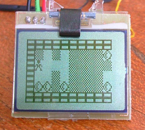
Now ive played with other LCD’s lots, but this one caught my attention because of the low power requirements (It runs from a single CR2032 Motherboard battery). I built the Temp probe as shown on the site and it worked well. I had several of the PCBs made, and decided that the others would be my own projects with the same hardware. I wondered what I could push this simple PIC and Nokia LCD into doing. I started by writing the base code from scratch. The simple routines to init the LCD and display on it. My first program shown above (The Unicorn) simply plotted a static picture from ROM onto the display.

3310 Nokia LCD

You can get the .hex file for the Unicorn picture on pic 12f675 here. The hardware as exactly as the original Temp probe spec (but you dont need temp probe, and set the jumper high).

You can get the source code here for the basic LCD setup.

For a laugh I thought id draw the HardOCP logo, you cant do much with 84×48 2colour!


For more detail: 3310 Nokia LCD & PIC12F683

The post 3310 Nokia LCD & PIC12F683 appeared first on PIC Microcontroller.
Simple Digital GPS Speedometer Using PIC16F877A with LCD Display

$
0
0

Speedometer is a speed measuring gauge used to calculate the speed of motor vehicles. They are mainly of two types- electronics and mechanical. Digital speedometer measures the speed and mileage in vehicles. Normally both types work on the principle of electromagnetism, however they have a disadvantage that they cannot be used if there are no wheels on the moving object. Here I am introducing a simple digital GPS speedometer using PIC16F877A with LCD display. This GPS speed meter provides the location, speed or other information of the moving objects based on GPS coordinates. The advantage of digital speedometer with GPS is that it can be placed easily anywhere on moving objects such as vehicles, running men, flying helicopter, aircraft, boats or ships. This system has an LCD Display which is used for monitoring the speed or any other information.Simple Digital GPS Speedometer Using PIC16F877A with LCD Display

Using GPS as a speedometer, you can monitor much more information like speed, time, position, satellite in use, no of satellite, satellite ID number and SNR (Signal to Noise ratio). The NMEA message from GPS gives the necessary information, since NMEA sends a line of data based on the GPS coordinates.

Circuit Diagram for GPS Speedometer Using PIC 16F877A Microcontroller

Components Required

  1. PIC16F877A
  2. GPS Module
  3. LCD 2×16
  4. Crystal (20MHz)
  5. Capacitor (22PFx2, 10uF)
  6. Resistor (1K)
  7. POT (10K)
  8. Power Supply

Working of Simple Digital Speedometer Using PIC 16F877A

As seen in the circuit diagram, our small GPS digital speedometer requires both 5 V and 12 V power supplies. This is because GPS module needs 12 V and other components require 5 V only.We can generate both these voltages from a single power supply circuit, so 12 V is enough for doing the GPS speed meter project with PIC 16F877A.

When power is supplied, GPS is turned ON and gets started to work.Simple Digital GPS Speedometer Using PIC16F877A with LCD Display schematic

GPS module continuously gives NMEA sentences based on the GPS coordinates. NMEA sentences from the GPS signal include time, position, GPS receiver operating mode, active satellites used, number of GPS satellites in view, satellite ID number, SNR (signal to noise ratio) values, azimuth values, elevation, position, date, time and speed of the GPS system with speedometer.

Every NMEA lines start with a dollar symbol ‘$’ which indicates starting of sentences. Every first sentence of GPS information will contain $GPXXX, which indicate global positioning system fixed values for the GPS system.

The information content for each NMEA sentence is shown in the table given below.


For more detail: Simple Digital GPS Speedometer Using PIC16F877A with LCD Display

The post Simple Digital GPS Speedometer Using PIC16F877A with LCD Display appeared first on PIC Microcontroller.
0-5V LCD volt meter using PIC16F877A

$
0
0

This PIC LCD volt meter project uses a PIC micro and an HD44870 LCD display. The analogue input is taken directly to the analogue input pin of the microcontroller without any other processing.

So the input range is from 0V to 5V – the maximum source impedance is 2k5 (for testing use a 1k pot). To improve the circuit add an opamp in front to present greater impedance to the circuit under test. The output impedance of the opamp will be low which is a requirement of the PIC analogue input.

Specification

 volt meter

Voltage range 0V – 5V
Input signal level TTL
Maximum input impedance 2k5

The LCD volt meter uses the microcontroller power supplies as reference voltages and so it is not likely to be very accurate (e.g. a 7805 5V regulator has an accuracy of 5%). You can make it more accurate by setting the scaling value in the software to match the power supply (measuring the supply using a voltmeter) (see Calibration later).

The most accurate way of all will be to use a voltage reference and feed this into RA3 as the positive reference value but this project simply provides a quick and easy way of measuring volts without circuit complexity.

The project mainly shows how to control and setup the software to read an analogue value from the first analogue port RA0.

Note when designing using the analogue inputs its a good idea to start from AN0 as there is only a limited set of ways that more analogue ports can be selected for use (see the chip data sheet – analogue inputs).

PIC lcd volt meter Hardware

You can use any PIC microcontroller that has an ADC and enough memory to hold the program.

The LED is pulsed after every ADC acquisition to indicate that the processor is alive – so you can tell if the software is active.

You can program the PIC in circuit through the ICSP connector.

For more detail: 0-5V LCD volt meter using PIC16F877A

The post 0-5V LCD volt meter using PIC16F877A appeared first on PIC Microcontroller.
Build your own “2-Wire LCD Interface” using the PIC16C84 microcontroller

$
0
0

2-Wire LCD Interface for the PICMicro

Alphanumeric LCD displays have become very popular for microcontroller applications because they can add a lot to a project in a variety of different ways. A text message giving the user instructions as well as feedback can make the application seem much more “professional” and easy to use. I like to use LCD’s to help debug applications, with breakpoints set to display variable and I/O conditions and they are a lot cheaper than using a microcontroller emulator. To top it off, surplus LCD’s can be found for a dollar or less.

The most popular LCD interface is the Hitachi 44780 based LCD controller chip which provides a fairly easy to work with interface and low power consumption. The major drawback of the interface is the perceived complexity of working with the interface. This perception has been promoted by the lack of good (i.e. well translated) and accurate datasheets and web site information.

Build your own 2-Wire LCD Interface using the PIC16C84 microcontrollerThis has been largely mitigated by the availability of a new data sheet from Hitachi; (available at here and user sites (such as my own at LCD Page with accurate information and example code that can be downloaded.

Often the biggest stumbling block to using alphanumeric LCD displays is the number of pins required to control them. For the Hitachi 44780, twelve pins are required from the microcontroller to interface to the display for it to work in eight bit mode. For many smaller microcontrollers, twelve pins are not available or will be better served in the application. To be fair, this can be reduced to six by using the 44780’s “Four Bit” mode, but this can still be more than acceptable for most applications.

A popular solution that only requires one pin from the microcontroller to the LCD is the use of “Serial LCD Interfaces” (such as Wirz Electronics “SLI-OEM” – http://www.wirz.com/) which convert “NRZ” serial data (either CMOS/TTL or RS-232 voltage levels) to the data and signals necessary for the Hitachi 44780 controllers.

Many of these products (such as the SLI-OEM) are excellent and can provide useful product interface and debugging information. The only drawback to them is the need for properly timed NRZ serial data which may be difficult or even impossible to guarantee in some applications.

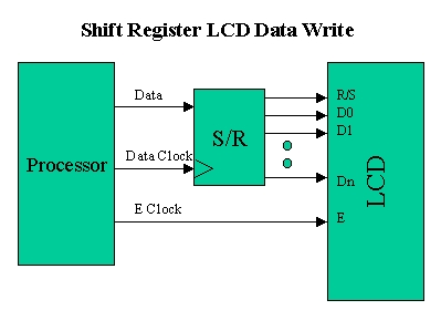
In this case, different approaches have to be made. The most popular one is to use synchronous serial data (requiring a “clock” and “data”) pin to load a serial-in/parallel-out shift register with the data bits and “R/S” pin information. The “E” Strobe Pin is driven directly by the microcontroller to latch in the data from the LCD. This is shown in the diagram below:

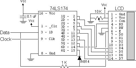
The project presented in this article is an enhancement of this circuit. By combining the shift register’s “Data Line” with the most significant bit of the shift register, the “E” Strobe can be implemented without resorting to a separate line for the function. The 1 K resistor and diode act as an “AND” gate. A schematic of the circuit is shown below.

The operation of the resistor/diode “AND” gate may not be immediately obvious. When the shift register bit is low, the diode pulls the connection to the “E” pin low. When the shift register bit is high, the diode will not cause any current flow from the connection at the “E” pin to the shift register. The resistor from “Data” to the “E” pin is a current limiting resistor. When the shift register bit is low and the data bit is high, then the current through the resistor will be limited to 5 mA (for a 5 Volt logic application). At the “Data” side of the resistor, the voltage will still be high, even though the diode is pulling the “E” pin low.

When both the “Data” line and the shift register bit are high, the “E” pin will be high. The “AND” circuit could be a TTL two input AND gate (such as a 7408), if you have an extra one available for your application. When I originally created this circuit, I used the same two transistor and two resistor circuit that I used for the 89C2051 emulator in “Programming and Customizing the 8051 Microcontroller”. I saw this “AND” equivalent circuit in an old copy of “Electronics Now” and found that it worked well in this application.

To load the shift register, it first has to be cleared to ensure that the “E” will not be strobed to the LCD inadvertently. This is done by first shifting in six “0”s to make sure that while the correct data is being loaded into the shift register, no “high” voltage level is passed to the “E” pin of the LCD.

 Build your own 2-Wire LCD Interface using the PIC16C84 microcontroller SchematicOnce this is done, the data can be shifted in. The diagram below shows how the shift register is initially cleared and then loaded with the data to be strobed (using “E”) into the LCD:

The application code, “2wirelcd.asm” is an assembler source file written for the PIC16C84. The file is written to be used with the “MPASM” assembler built into Microchip’s “MPLAB”. I wrote the code with the idea that it should be easily portable to any low-end or mid-range PICMicro without modification.

For the two I/O pins (“Data” and “Clock”), I “defined” them to allow you to use virtually any pins in your PICMicro application. I say “virtually any” because PORTA pin 4 (also known as “RA4”) is of “open drain” configuration and cannot source a positive voltage. The code itself is a very straightforward example of writing a 4-bit LCD application which displays the string “Hello” on the LCD display. The important difference between this code and a straight 4-bit LCD output is the “NybbleOut” subroutine, which is called twice by each of the “SendCHAR” and “SendINS” subroutines (which send characters and instructions, respectively, to the LCD).


For more detail: Build your own 2-Wire LCD Interface using the PIC16C84 microcontroller


The post Build your own “2-Wire LCD Interface” using the PIC16C84 microcontroller appeared first on PIC Microcontroller.

PIC 16C84 VT-52 Emulator for Linux

$
0
0

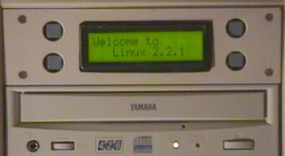
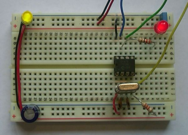
Features

  • Fits in one half height 5.25″ drive bay.
  • Back light 16 x 2 lines LCD (Hitachi Compatible) display.
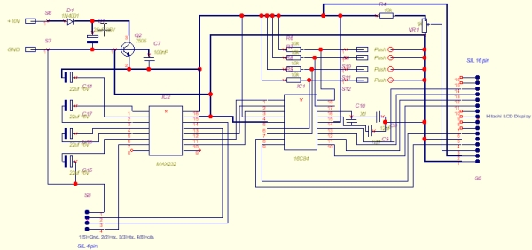
  • 4 Selection buttons, arranged so that it looks like an ATM machine.
  • RS232 19,200 baud connection to PC with Hardware handshaking (CTS).
  • Uses a subset of the standard VT-52 control codes to control the LCD.
  • 3.6864MHz crystal make baud rate calculations easy.
  • Should be easy to port to BSD, SCO OpenServer,
    SCO Unixware, SUN Solaris or anything that has a serial port.
  • Doesn’t use any fancy or hard to get parts, all available
    off the shelf from Maplin Electronics (UK). However, some of the spacers
    needed to be cut to fit.

PIC 16C84 VT-52 Emulator for LinuxWhy?!

If you have read the other pages on this site you’ll know that I’ve got a Linux machine on a shelf in my room that provides all sort of useful services. It’s got no monitor or keyboard, and sometimes this can be annoying. What I wanted was a small display that I could check on that state of the machine and perform some useful actions – like a controlled shutdown, mount or un-mount devices – that type of stuff.

I like electronics and a few years ago began experimenting with Microchip’s PIC16C84. I bought five of these devices for a knock down price and so I’m now putting them to use. The ’84 isn’t the best tool for the job as it lacks a UART, this is no big deal really – it just makes the software on the PIC more interesting.

Problems and Limitations

Reading RS232 is quite a CPU intensive operation for the ’84 as you must poll and sample the RS232 waveform in software in order to determine the whole byte. As soon as the PIC detects that a transmission is on its way it uses CTS to inform the host device not to send any more data until it is ready for more. This gives the PIC enough time to control the LCD or perform other in house tasks. Unfortunately there is a problem with this. 16550A PC serial port chipsets under Linux send 8 bytes then see if the remote device can handle any more. If you use this PIC on one of these serial ports only every 8th byte is correct, the rest are corrupt because they were sent while the PIC wasn’t ready. The solution to this problem is fortunately very easy to fix. You need to tell Linux to control the serial port like an old style 8250 that had no fancy buffers. So.

setserial /dev/ttyS1 uart 16450

will fix this problem on Linux, I’m not sure about other Unix’s.

Because of the polled serial reading it is possible for the start bit to arrive while the PIC is in the middle of the interrupt routine to poll the buttons. A corrupted byte (or two) is likely to be read. This doesn’t happen very often, if fact I’ve not seen it happen yet – but it’s statistically likely to happen. The solution to the is to use a real UART or a PIC with a UART. I’ve recently made some adjustment to the code to tighten the timing up, it’s now very unlikely to get corrupted characters.

What needs changing or fixing when you build the next version?

  1. Button repeat in the PIC code.
  2. Use round buttons to match the round holes!
  3. The display does not scroll, I’d need an extra control line to the LCD to do this which with the current PIC I don’t have. However, there are ways to get round this by multiplexing the LCD data lines with the buttons.
  4. Full duplex using a lower baud rate, and that should eliminate the need for hardware handshaking. 2400 baud might be OK…

PIC 16C84 VT-52 Emulator for Linux SchematicWhat VT-52 codes does it understand?

ESC E Clear display and reset cursor to top left.
ESC T not a VT code. This is something I’ve put in that displays a test pattern, used to check the RS232 output serial code in the PIC.
ESC H Resets the cursor to the top left, but does not clear the display.
ESC Y Position the cursor, format of the command is ESC Y (32+Y) (32+X) so ESC Y !! sets the cursor to 1,1.
ESC e Cursor visible.
ESC f Cursor off.

That’s it, there isn’t very much point implementing the rest, some code are impossible to do with the LCD anyway – like inverse video and colours.


For more detail: PIC 16C84 VT-52 Emulator for Linux

The post PIC 16C84 VT-52 Emulator for Linux appeared first on PIC Microcontroller.
Nokia 1100 LCD Interfacing with Microcontroller

$
0
0
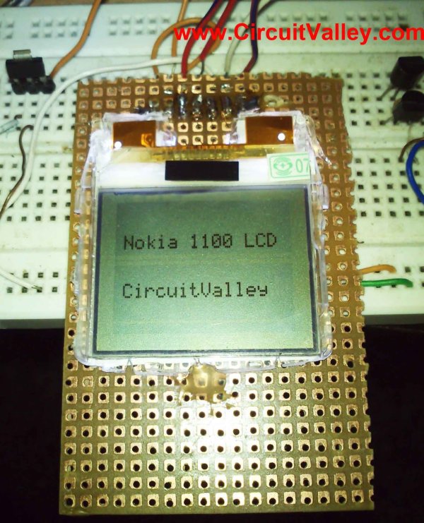
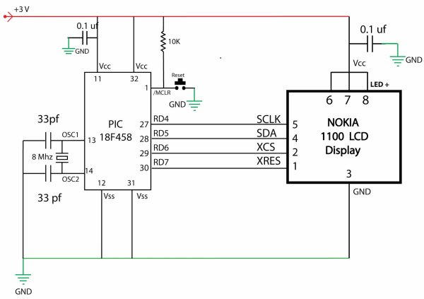
 Displaying content on a normal alphanumeric display is very limited ,we have to be limited with the font size and we can’t draw any graphics also. but convention Graphics lcd are really very expensive so here is the solution, you can use Nokia 1100 monochrome  LCD to display your large font text and graphics . the reason behind using this LCD is ,it is really very cheap and can be powered with 3 volts supply. so it is really good for battery powered application.
      Driver IC on this LCD panel is PCF8814 which even though has I2C protocol support – doesn’t use it. Instead it uses simple bit-banging mechanism for communication.Nokia 1100 LCD Interfacing with Microcontroller

 Project Description

however you can use almost any microcontroller (need a little bit extra circuit to work with mcu who doesn’t support 3v) do display content on this LCD, may be that micro controller is PIC , AVR or MSP 430 ,8051 but in this demonstration we will be using Microchip PIC 18F458 Microcontroller.
    The software program for this project will be written in C with MPLAB IDE , This LCD has a resolution of 96 x 65 pixels

 About LCD:-

Nokia 1100 Graphical LCD uses PCF8814 Controller chip From Philips. It is a chip-on glass(COG) with  9 pin (pin no 9 is not used) connector on the back side of the LCD . You can refer to its datasheet for more information about this controller. (CLICK HERE TO DOWNLOADPCF8814 Controller DATA SHEET).we will discuss only few main points here for out project purpose.

This LCD has  96 x 65 pixels , which mapped directly in the ram memory of the LCD, as shown in the figure blow

Nokia 1100 LCD Interfacing with Microcontroller schematic

The typical example of RAM is shown in the figure blow, The vertical axes area addressed form 0 to 8 with eight bits for each address when combining with x axes, it can be represented as bank.
The horizontal axes are addressed form 0 to 83 and each bit will refer the corresponding pixel in X direction.
Addressing Mode
 There are two type of addressing mode in this LCD
Vertical addressing Mode
In vertical addressing Mode each write instruction will increment the address in Y direction and then return to starting address
Horizontal addressing
horizal addressing each wire instruction will increment the address of X direction and return to starting address

For more detail: Nokia 1100 LCD Interfacing with Microcontroller

The post Nokia 1100 LCD Interfacing with Microcontroller appeared first on PIC Microcontroller.

Voltmeter Ammeter Kit – Blue Backlight LCD

$
0
0

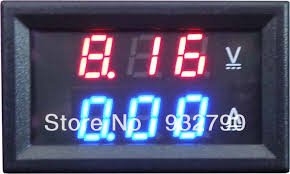
Voltmeter Ammeter is a great kit to measure voltage and current at the same time. It measures 0-70V or 0-500V voltage with 100mV resolution and current from 0 to 10A. It’s a perfect addition to any power supply, battery chargers and other electronic projects where voltage and current must be monitored. Kit uses PIC16F876A microcontroller with built-in ADC (Analog to Digital Converter) to sample voltage with current and display it on 16 x 2 backlighted LCD display. It comes with all the parts required to build high quality kit, including double-sided PCB with beautiful red solder mask and plated through holes. With slight modification it is possible to measure higher voltage and current. To measure voltage that is higher than 70 Volts simply replace R3 6.8K resistor with included 1K resistor. This will allow to measure up to 500 Volts. Voltmeter Ammeter Kit - Blue Backlight LCDTo measure current that is higher than 10A simply replace 0.1 Ohm 5W power resistor with higher wattage resistor. For example 20W 0.1 Ohm resistor will allow to measure up to 20 Amps. Kit can also measure AC voltage if rectifier bridge is added to voltage input as well as measure and be supplied by the same power source.

Specifications
  Voltage Supply: 6 – 30V
  Current Consumption: 30mA
  Voltage Input: 0 – 70V / 0 – 500V
  Current Input: 0 – 10A

Component List
1x 16 x 2 LCD Display with Blue Backlight
1x PIC16F876A – Programmed microcontroller
1x High Quality PCB with red solder mask and plated through holes
1x 28-DIP IC Socket
1x 4MHz Resonator Voltmeter Ammeter Kit - Blue Backlight LCD schematic
1x 16 x 1 Gold Plated Male Header
1x 16 x 1 Gold Plated Female Header
1x 4 x 1 Gold Plated Header
1x LM7805 5V Voltage Regulator
1x 10K Trimmer Potentiometer
1x 4 x 10K Network Resistor
2x 100K 1% Metal Film Resistor
2x 6.8K 1% Metal Film Resistor
1x 1K 1% Metal Film Resistor
1x 10 1% Metal Film Resistor
1x 0.1 Ohm 5W Power Resistor
1x 100nF Ceramic Capacitor
1x 10uF Panasonic Capacitor
1x Manual with Schematic


For more detail: Voltmeter Ammeter Kit – Blue Backlight LCD

Current Project / Post can also be found using:

  • microchip potentiometr to lcd
  • pic16f84a project to display an lcd display

The post Voltmeter Ammeter Kit – Blue Backlight LCD appeared first on PIC Microcontroller.

Low cost LCD module interface with optional LED backlight using PIC18F452

$
0
0

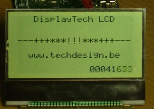
Here are the technical specifications:

  • LCD resolution: 128 x 64 pixels
  • LCD manufacturer: DisplayTech.
  • LCD model 1: 64128COG-FA-BC (no backlight)
  • LCD model 2: 64128G-FC-BW-3 (white LED backlight)
  • On-glass lcd controller KS0713, with 30 pins connector.
  • Very low power operation (less than 1mA @3V)
  • Fast serial interface (only 8 wires needed)
  • Molex miniature connector.
  • LCD: dimensions: 56 x 41 mm
  • PCB interface: Dimensions: 44 x 18 mm

LCD module


These two LCD modules can be bought in our online shop. You’ll need the interface described below and a PIC microcontroller to get these LCD modules running.

PIC example Source code (CCS C) , pcb layout and schematics (Eagle) available.  Last update: March 24, 2007.

PIC software example: routines

ccs routine example explanation
LCD initialization dt_lcd_init(); init parameters needed after power on
Clear screen dt_lcd_clear_screen(); resets all pixels, needed after power on
Cursor position set dt_lcd_gotoxy(0,5); goto cursur location x= 0..127 PIXEL COLUMNS // y= 0..7 CHAR. ROWS
Write text to LCD printf(dt_lcd_printchar,” DisplayTech LCD”); show simple unformatted text


Downloads: right-click & save as

Interface: Eagle PCB layout: 042 – 004.brd  – March 24, 2007.

 Interface: Eagle Schematics: 042 – 004.sch  – March 24, 2007.


 PIC CCS example: source code: 042_v01.zip for 18f452 @ 20MhZ – March 24, 2007.

 PIC CCS example:Hex file: 042_v01.hex for 18f452 @ 20MhZ – March 24, 2007.


For more detail: Low cost LCD module interface with optional LED backlight using PIC18F452


Current Project / Post can also be found using:

  • lcd based projects in pic
  • two dice miniproject in PIC

The post Low cost LCD module interface with optional LED backlight using PIC18F452 appeared first on PIC Microcontroller.

Serial LCDs you can make your own using PIC12F683

$
0
0

HD44780 based LCD displays are very popular for embedded projects because they are cheap, easy to interface, can display characters, consume power lot less than seven-segment displays, and most of the present day compilers have in-built library routines for them. However, the only disadvantage is that they require at least 6 I/O pins of microcontroller. Well, you may ask, isn’t that less than what seven-segment displays require? Yes, that’s true but there are circumstances where you don’t have left enough pins for LCD display. For example, if you are going to design a temperature sensor based on a PIC12F683 microcontroller, which has just 6 I/O pins, you won’t have pins for interfacing a LCD. One solution for cases like that is to use serial LCD’s. Serial LCD’s available in the market cost more than double of HD44780 based standard one. The serial LCD’s still have the standard LCD module but it has an extra built-in driver module that receives data/command from a host microcontroller in serial format and convert it to appropriate parallel format suitable for HD44780 driver input.

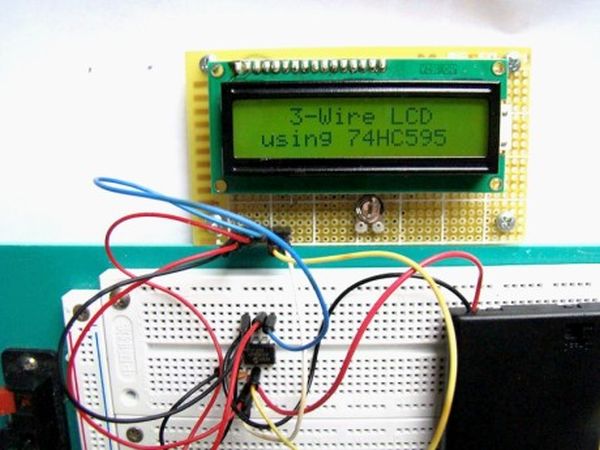
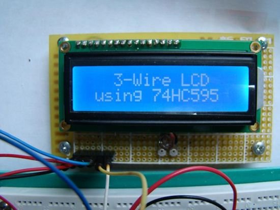
3 Wire LCD

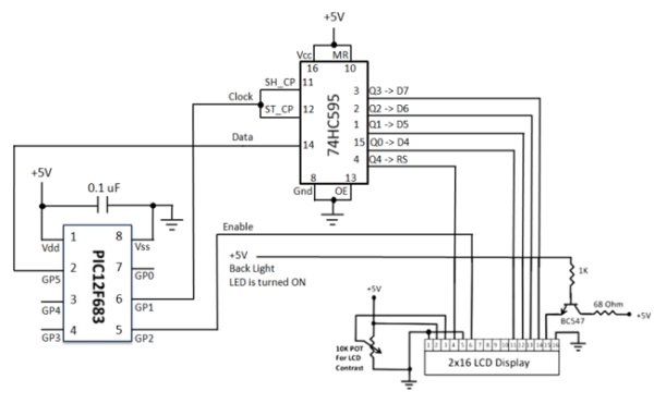
The goal of this project is to show how to make a 3-wire serial LCD driver for low pin-count microcontrollers like PIC12F series using a serial-in parallel-out shift register (74HC595 in this case). PIC12F683 has been chosen here to test the end product. Since 74HC595 is just a shift register with no intelligence of its own, the burden goes to the host microcontroller (PIC12F683) to appropriately transfer the LCD character/command data and control signals in serial format. This part of the intelligence is embedded in the firmware inside PIC12F683. So, a portion of program flash memory inside PIC12F683 is sacrificed for this purpose. The required three pins of PIC12F683 performs following functions.

  1. Serial data transfer to 74HC595
  2. Clock signal for the Shift/Storage register
  3. Enable signal to HD44780 LCD Module

74HC595 Shift Register

74HC595 is a high-speed 8-bit serial in, serial/parallel-out shift register. It also has a storage register and 3-state outputs. The two registers (shift and stoarge) have separate clocks, SH_CP and ST_CP respectively. Data in the shift register is shifted on the positive-going transitions of SH_CP, and the content of shift register will be transferred to the storage register on a positive-going transition of the ST_CP. If both the clocks are together, the shift register will be one clock ahead of the storage register. The output enable (OE) pin, when pulled Low, enables the 8-bit data of the storage register to show up at the parallel output (Q0-Q7).

SH_CP and ST_CP clocks are tied together for this purpose and are driven together by a microcontroller pin. So, the storage register output (Q0-Q7) is 1 clock behind the shift register, and an additional clock pulse is required after the last bit is fed to the serial input so that it would appear at the output.

HD44780-based character LCD

HD44780 based character LCD displays use 14 wire connections: 8 data lines (D0-D7), 3 control lines (RS, E, R/W), and three power lines (Vdd, Vss, Vee). Some LCDs come with backlight features that help reading display data in low illumination conditions. They have two additional connections  (LED+ and LED-).


For more detail: Serial LCDs you can make your own using PIC12F683

The post Serial LCDs you can make your own using PIC12F683 appeared first on PIC Microcontroller.

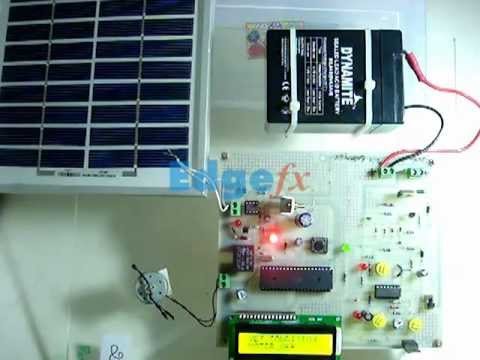
Solar power auto irrigation system using microcontroller

$
0
0

Solar power auto irrigation system using microcontroller, In this article you will learn about auto irrigation system. Whats is irrigation system? What is auto irrigation system? How to make irrigation system automatic? How to use microcontroller to make intelligent and automatic? Circuit diagram of solar power auto irrigation system using pic microcontroller. This project just give you idea about solar power auto irrigation system. It is for low power application. But you can make it according to your requirement. Basic idea and implementation remains same.

Page Contents hide1 What is irrigation system ?
2 What is auto irrigation system ?
3 What is solar power auto irrigation system ?
4 Circuit diagram of solar power auto irrigation system using pic microcontroller :
Solar power auto irrigation system using microcontroller
4.1 Solar charge controller :
4.2 Moisture sensor :
4.3 LCD display :

What is irrigation system ?

Irrigation system is basically a way to give water to land or plants. In agriculture field it is very important to provide water to plants in case of lack of rain and deficiency of water under the earth. It is very important to give proper water to plants to make their growth effective. Therefor irrigation system is used to provide proper water to plants and lands.

What is auto irrigation system ?

Auto irrigation system is very important in the field of agriculture. In the field of agriculture it is very important to maintain level of water or moisture in soil where corps are planted. Excess or deficiency in water may harm the growth of plants which results in loss of farmers. To solve this problem, auto irrigation system is designed. Auto irrigation system keep information about moisture level in land and keep moisture to permissible limit. Moisture sensor is used to measure moisture level  in soil. According to measured moisture level, water pump turn on or off. I will explain it in more detail later.

What is solar power auto irrigation system ?

As we know it is difficult in agriculture field  to control water pumps manually. One have to stay in fields to turn on and off. In many countries where electricity is main issue, villagers usually don’t have facility of electricity . In that case solar power is used to power water pumps. In solar power auto irrigation system, solar charge controller is used to store dc power of solar panels in batteries. This stored battery is used to power water pumps automatically. I will explain later what is meant there by automatically.

Circuit diagram of solar power auto irrigation system using pic microcontroller :

Circuit diagram of solar power auto irrigation system is given below. I have explained main components of this project also along with circuit diagram.

Above circuit diagram shows the main components of solar power irrigation system. I have explained main components below :

Solar charge controller :

Solar charge controller is used to charge 12 volt battery. The basic purpose of solar charge controller is to avoid over charging and over discharging of battery. There are three types of solar charge controller available in market. 24 volt solar panel is used in this project which charge 12 volt 7.2AH battery with the help of solar charge controller.Solar power auto irrigation system using microcontroller schematic

Moisture sensor :

Moisture sensor is main component of this project which is used for the measurement of moisture in soil. There are many moisture sensors available in market. You can purchase any of them. But the working principle of  all them almost remains same. They work on the principle of change in resistance. Basically moisture sensor is a metallic strip. Resistance of metallic strip changes according to moisture level in soil. If moisture is high, resistance will be low and if moisture in soil is low, resistance will be high. Because moisture increases the conductivity of metallic strip. PIC microcontroller is used to measure change in resistance of moisture sensor. This change in resistance is used to turn on or turn off dc water pump with the help relay interfacing with microcontroller.


For more detail: Solar power auto irrigation system using microcontroller

The post Solar power auto irrigation system using microcontroller appeared first on PIC Microcontroller.

Interfacing LCD Modules with PIC Microcontrollers.

$
0
0

A large number of embedded project require some type of user interface. This includes displaying numerical, textual and graphical data to user. For very simple numerical display we can use 7 segment displays. If the requirement is little more than that, like displaying some alphanumeric text, we can use LCD Modules. They are cheap enough to be used in low cost projects. They come in various sizes for different requirement. A very popular one is 16×2 model. It can display 2 lines of 16 characters. Other models are 16×4,20×4, 8×1,8×2 etc.

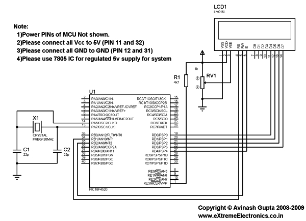
In this tutorial we will learn how we can use such modules with Microchip PIC Microcontrollers. Here I will present my LCD library which you can use to create LCD based application/projects quickly. For demo I will use PIC18F4520 Microcontroller but you can use any PIC18 MCU. But you have to calculate the CONFIG values for correct setting and CPU clock selection etc. That means the chip should be configured correctly. See datasheet for more info on CONFIG bytes.

Interfacing LCD Modules with PIC Microcontrollers. MPLAB Project Creation

First create a MPLAB project as described in this tutorial. Name the project LCD. Also add a main file called “lcd_test.c”. To use my LCD library you need to add it to your project. Just copy/paste the following files to your project folder.

Header Files

  • lcd.h
  • myutils.h

Source File

  • lcd.c

How to add files to MPLAB Project is described here.

Now you are ready to the library functions to interact with the LCD module.

Interfacing LCD Modules with PIC Microcontrollers SchematicSample Program (lcd_test.c)

/********************************************************************

16X2 ALPHANEUMERIC LCD INTERFACING LIBRARY TEST PROGRAM

---------------------------------------------------------

A testing program for our LCD library.

Easy to use library for interfacing 16x2 lcd in 4 bit mode.
MCU: PIC18FXXXX Series from Microchip.
Compiler: HI-TECH C Compiler for PIC18 MCUs (http://www.htsoft.com/)

Copyrights 2008-2009 Avinash Gupta
eXtreme Electronics, India

For More Info visit
http://www.eXtremeElectronics.co.in

Mail: me@avinashgupta.com

********************************************************************/
#include <htc.h>

#include "lcd.h"

//Chip Settings
__CONFIG(1,0x0200);
__CONFIG(2,0X1E1F);
__CONFIG(3,0X8100);
__CONFIG(4,0X00C1);
__CONFIG(5,0XC00F);
//Simple Delay Routine
void Wait(unsigned int delay)
{   for(;delay;delay--)      __delay_us(100);}void main()
{   //Let the Module start up   Wait(100);   //Initialize the LCD Module
   LCDInit(LS_BLINK);   //Clear the Module
   LCDClear();   //Write a string at current cursor pos
   LCDWriteString("Good Is Great !!");

   Wait(20000);   //Now Clear the display
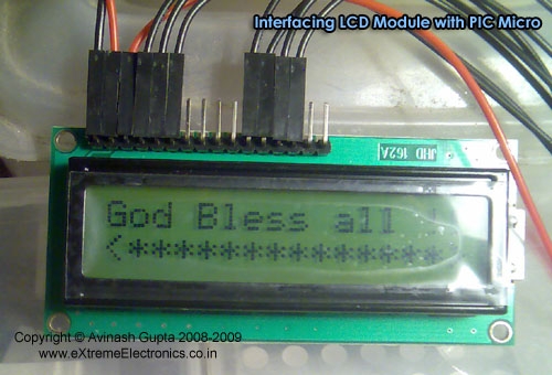
   LCDClear();   LCDWriteString("God Bless all !!");
   //Goto POS (X=0,Y=1 i.e. Line 2)
   //And Write a string
   LCDWriteStringXY(0,1,"<**************>");
   Wait(20000);   //Write Some Numbers
   for(char i=0;i<100;i++)
   {         LCDClear();  LCDWriteInt(i,3); Wait(3000);   }
   LCDClear();   LCDWriteString("    The  End    ");
   //Loop Forever   while(1);}


For more detail: Interfacing LCD Modules with PIC Microcontrollers. 

The post Interfacing LCD Modules with PIC Microcontrollers. appeared first on PIC Microcontroller.


Open Source 3.2” TFT Smart Display

$
0
0

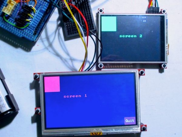
This project is an open source 3.2″ Smart TFT display board. The board is based on a PIC32 and a 3.2′ TFT with touchscreen (ILI9320 controller, using 16bits PMP). The software has two main parts. One that produces the 2D functions and a GUI with various widgets (buttons, check boxes, sliders etc).

Open Source 3.2” TFT Smart Display

Description

A new version of 3.2″ TFT Smart Display project can be found here

In the beginning, I just wanted to play with these cheap TFT screens available on eBay (displaying some pictures & text, nothing more); step by step, I finally designed a PCB and a built a consequent software with many 2D basic functions and even a small GUI.

The board is based on a PIC32 and a 3.2′ TFT with touchscreen (ILI9320 controller, using 16bits PMP). The PCB is 4.9 x 4.9 cm, 2 layers (=> $15 / 10 units at seeedfusion).

Schematic

Schematic Open Source 3.2” TFT Smart Display

About the software: I’ve first tried to use some parts of code provided by Microchip, but their library looks like quite complex from my point of view (some files with more than 5k lines, with too much #ifdef…. ><“). As a result, I rewrote a new software, from scratch; this software is composed of 2 main parts:

– P2D: 2D functions (drawing a line, put some texts & sprites, draw filled polygons, memory buffering…)

– GUI: small GUI with some basic widgets (buttons, checkbox, graph, …). Each widget has generic attributes (disabled, notified, focused, …), can be grouped and linked to signals (e.g. emit a signal when the widget is pressed)

The project is under OSHW / GPL3.

For more detail:  Open Source 3.2” TFT Smart Display

Current Project / Post can also be found using:

  • i/o requirement of microcontroller of motor control with LCD display and LED indicator

The post Open Source 3.2” TFT Smart Display appeared first on PIC Microcontroller.

LCD Serial Terminal using PIC16F84

$
0
0

LCD Serial Terminal

Introduction:
In the 1980s a serial terminal was a big thing with a picture tube and keyboard. You used it to communicate with a computer by RS-232 cable or with a modem. In this century, we still sometimes have need for a serial terminal, and we’ll typically use a personal computer running a terminal program (Hyperterminal, bundled withWindows, is a terminal program). This project is a self-contained serial terminal using a PIC16F84 microcontroller chip, an inexpensive LCD character display, a keypad, and very little else. It is full-duplex, meaning keypresses cause RS-232 output, and RS-232 input makes characters appear on the LCD. If you connect the RS-232 output to the input you can see the keys as you press them, without connecting to anything else (that’s called “looping back”).

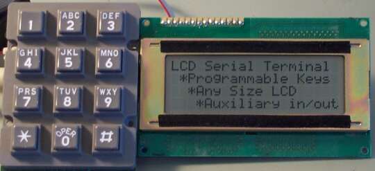
LCD Serial Terminal

Project Description:
The picture above doesn’t show the electronics, just a keypad and LCD display. The electronics is on a small board behind the LCD. This LCD is a 4 line by 20 character intelligent LCD display. Displays from 1×8 to 4×20 or 2×40 and pretty much anything in between are compatible. I paid less than US$10 for this display from All Electronics. The keyboard you use should be a matrixed keyboard or keypad with up to 5 rows and 4 columns (20 keys maximum).

This small PC board is the terminal itself. Someday I will document a PC board design, but currently I am only making available the schematic diagram, source code for the PIC16F84, and compiled hex code for a typical configuration so you can quickly test it out. The source code is in C and very easily configured for different baud rates, LCD and keypad configurations. The program should be compiled with Hi-Tech PICC. A free version supporting the PIC16F84 called “PICLITE” is available and works fine.

The mapping of the keys is fully configurable, and each key can also be configured for one of four different modes. Each key is allowed to have a primary code and a secondary code. Depending on what mode is chosen, the secondary code might be sent when the key is released, or when the key is held more than one second, etc. Key repeat is also programmable, and each key can have a different mode.

Many cursor movement features are implemented, all the standard ones (backspace, carriage return etc.) and if you tell the program your LCD format, text will flow from line to line.

For more detail: LCD Serial Terminal using PIC16F84

The post LCD Serial Terminal using PIC16F84 appeared first on PIC Microcontroller.

Serial LCD Library using PIC16C84

$
0
0

Here is a library to interface your PIC code to an LCD that is controlled via a serial line. One such LCD is available from Scott Edwards Electronics. There are many others, and the code shown here can easily be adpated to other LCD displays by changing some defines.

Serial LCD Library

The following files are referenced below, but for simplicity I’ve listed them here for download:

  • LCDlib.tar.gz is my entire LCD library and associated test source code in gzip’d tar format.
  • LCDlib.zip is my entire LCD library and associated test source code in zip format for Windows PCs.
  • lcd.c the library C source.
  • lcdtest1.c tests printing an integer in decimal and hex format (lcdtest1.hex).
  • lcdtest2.c tests positioning the cursor for printingt (lcdtest2.hex).
  • lcdtest3.c tests scrolling the LCD display left and rightt (lcdtest3.hex).
  • lcdtest.jpg a schematic showing how to wire the PIC to the serial LCD module.

The following routines are defined:

  • void lcd_putc(char c) send the byte c to the LCD
  • void lcd_clear(void) clears the LCD screen
  • void lcd_home(void) homes the LCD cursor
  • void lcd_puts() print a string **UNIMPLEMENTED**
  • void lcd_printhex(char c) prints byte c as a 2 digit hex character
  • void lcd_printdec(char c) prints byte c as a decimal digit string
  • void lcd_printbin(char c) prints byte c as a binary string
  • void lcd_scroll_left(char n) scrolls LCD screen left n positions
  • void lcd_scroll_right(char n) scrolls LCD screen right n positions
  • void lcd_goto(char row, char col) goto a location

The LCDPORT and LCDPIN constants define which port and logical pin the serial LCD is connected to. By default they are set to PORTA and pin 1 which is the RA1 output on phsyical pin 17 of a PICC84.

If you connect the serial LCD to a different port and pin then you must change the definitions in the lcd.c file.

void lcd_putc(char c) – send a byte to the LCD
This routine is the heart of the LCD library: it will send a byte specified in the argument c to the LCD connected to the port defined by LCDPORT and pin LCDPIN. All the other routines use this code. lcd_putc() assumes that the LCD is running at 9600 baud, 8-N-1 serial settings. If your LCD is running at a different baud rate, or you have a faster PIC, you will have to adjust the timing loop starting at lcdtxloop. The lcd_putc() routine places a 10ms pacing delay between each character.
void lcd_clear(void) – clear the LCD screen
Building upon the lcd_putc() routine is easy, as this routine shows. We simply send the byte sequence that clears the display.
void lcd_home(void) – home the LCD cursor
Sends the byte sequence that homes the LCD cursor to the top left hand corner.
void lcd_printhex(char c) – print byte as hex
Print a byte value on the display as 2 hex characters. For example, the value 255 would be printed as FF. The code prints the hi nibble first (the upper 4 bits of the byte), followed by the lower nibble.
void lcd_printdec(char c) – print byte as decimal
Print a byte value as a decimal string. For example, the value 123 is printed as the characters “123”. This function performs repeated subtractions: starting at 100, we subtract until the value left is less than 100. We then repeat the loop for 10’s. Whatever is left is the units value. Effectively, this routine performs division by repeated subtraction. The output of lcd_printdec() is always 3 digits long: 001 as against just 1.
void lcd_printbin(char c) – print byte as binary
This routine prints a binary representation of a byte. For example, 129 would be printed as 10000001. 8 bits are always printed, which means that the value may have leading zeros: 5 would be printed as 00000101.
void lcd_scroll_left(char n) – scroll screen left
Scroll the LCD display left n positions. The effect of this command depends a lot on the type of LCD display you have.
void lcd_scroll_right(char n) – scroll screen right
Scroll the LCD display right n positions. The effect of this command depends a lot on the type of LCD display you have.


For more detail: Serial LCD Library using PIC16C84

The post Serial LCD Library using PIC16C84 appeared first on PIC Microcontroller.

100MHz frequency counter with PIC16F628A – LCD Display

$
0
0

This project shows how to build a very simple yet very useful tool that every DIY enthusiast should have in his lab: a 100MHz+ frequency counter.

The schematic is fairly simple and straightforward and uses a PIC16F628A microcontroller for measuring frequency and a high speed comparator for signal amplification and conditioning.

The microcontroller uses its internal 4MHz oscillator for the CPU clock. Timer1 uses an external crystal resonator (watch crystal) with 32768Hz frequency for setting the 1 second time base.

100MHz frequency counter with PIC16F628A – LCD Display

Timer0 is used to count the input signal at pin RA4.

The max frequency of Timer0 is 1/4 of the CPU clock which is 1MHz, but there is internal prescaler and it can be set from 1 to 256. In theory this can allow the input signal to be up to 256MHz. On the other hand, in the datasheet of 16F628A there is a requirement for the input pulse at RA4 to be with minimum width of 10ns which is 100MHz frequency. So the maximum frequency can be between 100Mhz and 256MHz. I checked with two different PIC16F628A and they easily go over 200Mhz barrier.

In order to achieve the maximum possible resolution, the input signal is probed for 0.125 seconds and the prescaler value is computed accordingly. This way when input frequency is below 1Mhz the resolution will be 1Hz.

The most important part for the accuracy of the frequency counter is the time base setting circuit – crystal resonator X1 and capacitors C4 and C5. C4 and C5 values can be between 33pF and 62pF and the crystal frequency can be fine tuned with them.

The input of the schematic is feed through a high speed comparator. In order to switch with 100+ Mhz frequency the comparator must have propagation delay bellow 5ns. In this schematic I used Texas Instruments TLV3501 with 4.5ns delay. This was cheapest high speed comparator I was able to find (2.5 euro).

The two inputs of the comparator are set at about 1/2 of power supply voltage with 15-25mV difference between them so any AC signal with higher voltage will start switching the comparator.

If there isn’t input signal the output of the comparator stays low. If we connect a signal source to the positive input, when the signal goes over +20mV the comparator switches high (5V), when signal goes bellow +20mV comparator switches back to 0V. So whatever signal we fed to the input, the output is square wave 0V-5V with the same frequency as the original signal.

The output of the comparator is fed directly to the RA4 pin of the microcontroller.

The input is protected with 1k resistor and two diodes limiting the voltage to ±0.7 V. The input impedance for low frequencies is equal to R1 – 47k. For VHF range maybe it is good idea to replace it with 50 Ohm value.

The schematic can be powered by 9V battery or any other DC voltage from 7V to 15-20V. LM78L05 or LM2931-5.0 IC is used for regulating the voltage down to 5V. There is simple soft ON/OFF circuitry with a dual P- and N-MOS transistor. When button is pressed the P-MOS transistor is switched on and the microcontroller is powered and its first instruction is to set RB4 high which switch the N-MOS transistor on and the power stays on. If the button is pressed again RB5 goes low and the microcontroller sets the RB4 low and this way switch the power off. The microcontroller also auto switch the power off after a certain amount of time (3min 40sec).

The schematic have fairly low power consumption – with no input signal the supply current is 7-8mA and goes up to 20mA with 200+MHz input signal. If the display is too dark, the back light can be adjusted by decreasing the value of the R9 resistor. This of course will increase the current consumption.

The program for the microcontroller is written in C and is compiled with MikroC for PIC

SchematicSchematic 100MHz frequency counter with PIC16F628A  LCD Display

For more detail: 100MHz frequency counter with PIC16F628A – LCD Display

The post 100MHz frequency counter with PIC16F628A – LCD Display appeared first on PIC Microcontroller.

3-Wire Serial LCD using a Shift Register

$
0
0

Introduction

HD44780 based character LCDs require at least 6 I/O lines from microcontroller to display data. Therefore, they are not suitable for low-pin microcontrollers like PIC12F series microchips. In this project, I am going to show how to drive an HD44780 based LCD display with only 3 pins of a microcontroller. I am going to demonstrate it with PIC12F683 microchip. The character data and command from the microcontroller is transferred serially to a shift register (74HC595), and the parallel output from the shift register is fed to LCD pins.

About 74HC595

74HC595 is a high-speed 8-bit serial in, serial or parallel-out shift register with a storage register and 3-state outputs.

The shift register and storage registers have separate clocks, SH_CP and ST_CP respectively. Data in the shift register is shifted on the positive-going transitions of SH_CP, and the content of shift register will be transferred to the storage register on a positive-going transition of the ST_CP. If we tie both the clocks together, the shift register will always be one clock ahead of the storage register. The 8-bit data of the storage register will appear at the parallel output (Q0-Q7) when the output enable (OE) is low.3-Wire Serial LCD using a Shift Register

In this project, SH_CP and ST_CP are tied together. So, if we want to receive a serially transferred 8-bit into parallel form at Q0-Q7, an extra clock pulse is required after transmitting the 8-th bit of serial data because the clocks are tied and the storage register is 1-clock behind the shift register.

HD44780-based character LCD

All HD44780 based character LCD displays are connected using 14 wires: 8 data lines (D0-D7), 3 control lines (RS, E, R/W), and three power lines (Vdd, Vss, Vee). Some LCDs may have LED backlight and so they may have additional connections (usually two: LED+ and LED-).
Rajendra Bhatt rajbex@yahoo.com
4723

Photo_4

Introduction

HD44780 based character LCDs require at least 6 I/O lines from microcontroller to display data. Therefore, they are not suitable for low-pin microcontrollers like PIC12F series microchips. In this project, I am going to show how to drive an HD44780 based LCD display with only 3 pins of a microcontroller. I am going to demonstrate it with PIC12F683 microchip. The character data and command from the microcontroller is transferred serially to a shift register (74HC595), and the parallel output from the shift register is fed to LCD pins.
About 74HC595

74HC595 is a high-speed 8-bit serial in, serial or parallel-out shift register with a storage register and 3-state outputs.

Pinout_1

The shift register and storage registers have separate clocks, SH_CP and ST_CP respectively. Data in the shift register is shifted on the positive-going transitions of SH_CP, and the content of shift register will be transferred to the storage register on a positive-going transition of the ST_CP. If we tie both the clocks together, the shift register will always be one clock ahead of the storage register. The 8-bit data of the storage register will appear at the parallel output (Q0-Q7) when the output enable (OE) is low.

In this project, SH_CP and ST_CP are tied together. So, if we want to receive a serially transferred 8-bit into parallel form at Q0-Q7, an extra clock pulse is required after transmitting the 8-th bit of serial data because the clocks are tied and the storage register is 1-clock behind the shift register.
HD44780-based character LCD

All HD44780 based character LCD displays are connected using 14 wires: 8 data lines (D0-D7), 3 control lines (RS, E, R/W), and three power lines (Vdd, Vss, Vee). Some LCDs may have LED backlight and so they may have additional connections (usually two: LED+ and LED-).

Pinout_2

Providing detail explanation of individual LCD pin doesn’t fall within the scope of this project. If you are a beginner with LCD, I recommend to read these two articles first from Everyday Practical Electronics magazine : How to use intelligent LCDs

Part 1: http://lcd-linux.sourceforge.net/pdfdocs/lcd1.pdf

Part 2. http://lcd-linux.sourceforge.net/pdfdocs/lcd2.pdf
Circuit Diagram

The hardware part of this project is fairly simple. The challenging part is to write the driver software that is responsible for a proper sequence of operations required to serially transfer character data and command to 74HC595 serial-in parallel-out shift register. The shift register parallel output is then connected to LCD data lines (D4-D7) and RS control pin. This arrangement requires 3-pins of microcontroller to display character data on a parallel LCD display: 2 pins for providing Clock and Data to 74HC595, and 1 pin for enable control (E) pin of LCD module. Since the data transfer uses 4-bit mode, any 8-bit command or character data is sent in two steps: send the higher nibble first, and then the lower nibble. The R/W control pin is grounded, and therefore no data or status read from the LCD module is possible in this case.

The SH_CP (11) and ST_CP (12) clock inputs of 75HC595 are tied together, and will be driven by one microcontroller pin. Serial data from microcontroller is fed to the shift register through DS (14) pin. OE (13) pin is grounded and reset pin MR (10) is pulled high. Parallel outputs Q0-Q3 from 74HC595 are connected to D4-D7 pins of the LCD module. Similarly, Q4 output serves for RS control pin. If the LCD module comes with a built-in backlight LED, it can simply be turned ON or OFF through LED control pin shown above. Pulling the LED pin to logic high will turn the back light ON.3-Wire Serial LCD using a Shift Register schematic

Software

A first, a bit of data fed to DS pin of 74HC595 appears at Q0 output after 2 clocks (because SH_CP and ST_CP are tied). So, sending 4-bit data (D4-D7) and an RS signal require 6 clock pulses till they appear at Q0-Q4 outputs respectively. When the LCD module is turned ON, it is initialized in 8-bit mode. A number of initializing commands should be sent to operate the LCD module in 4-bit mode. All the driver routines that are discussed here are written in mikroC compiler. They work only for a 16×2 LCD module. User can modify the initialization operations inside the Initialize_LCD() routine to account for other LCD configurations. The driver routines and their functions are described below. 

– Initialize_LCD() : It initializes the LCD module to operate into 4-bit mode, 2 lines display, 5×7 size character, display ON, and no cursor.

– Write_LCD_Data() : Sends a character byte to display at current cursor position.

– Write_LCD_Cmd() : Write a command byte to the LCD module.

– Write_LCD_Nibble() : Data or command byte is sent to the LCD module as two nibbles. So this function routine takes care for sending the nibble data to the LCD module.

– Write_LCD_Text() : This routine is for sending a character string to display at current cursor position.

Position_LCD() : To change the current cursor position

At the beginning of your program, you need to define Data_Pin, Clk_Pin, and Enable_Pin to the chosen microcontroller ports. I am going to demonstrate here how to use these driver routines to display two blinking character strings, Message1 and Message2, at different locations. I am going to test our serial LCD module with PIC12F683 microcontroller. The test circuit is shown below.

Note: My PIC12F683 Settings

Running at 4 MHz internal clock, MCLR disabled, WDT OFF.

Clock, Data, and Enable lines are served through GP1, GP5, and GP2 ports.

For more detail: 3-Wire Serial LCD using a Shift Register

Current Project / Post can also be found using:

  • i2c lcd pic asm

The post 3-Wire Serial LCD using a Shift Register appeared first on PIC Microcontroller.

Viewing all 253 articles
Browse latest View live


<script src="https://jsc.adskeeper.com/r/s/rssing.com.1596347.js" async> </script>