Quantcast
Channel: LCD Projects - PIC Microcontroller
Viewing all 253 articles
Browse latest View live

Interfacing VFD with PIC Microcontroller

$
0
0

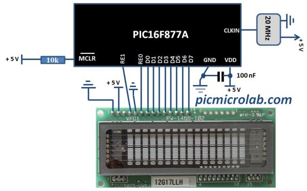
Vacuum fluorescent display can be a good alternative to a Liquid-crystal displays in some applications. They have a number of advantages over LCD like extended temperature range and excellent contrast in high brightness environment. The main disadvantage is higher power consumption making them less attractive in battery operated devices.Interfacing VFD with PIC Microcontroller In this post I’ll show you how you can use this type of display with microcontroller. You can purchase them on Ebay as I did here.CU16025 VFD module was used for this purpose as a direct replacement for 2×16 LCD display. Although the manufacturer of these modules provides some code examples I’ve used my own driver code (originally written for a LCD) and a parallel 8 bit connection to interface this display with PIC16F877A microcontroller. I’ve adapted assembly language subroutine that I wrote earlier for VFD module initialization and for sending data/command. The code was written in C in MPLAB X using XC8 compiler. The same subroutine was also used in VFD Voltmeter project. As you can see from the schematic below 2 PORTs were used to control the display. PORTD for data/command and PORTE for RS and Enable lines.Interfacing VFD with PIC Microcontroller schematich

The code consist of 3 main functions: Display initialization, WriteDataVFD , WriteCommandVFD. Command for example can be an address of one of the segments and data is the character you want to display in ASCII. Comments in the source code should provide you  with more detailed explanation on each instruction. Click here to download the code.


For more detail: Interfacing VFD with PIC Microcontroller

The post Interfacing VFD with PIC Microcontroller appeared first on PIC Microcontroller.


PIC Microcontroller project – 24 hour clock and thermometer displayed via 16f690 microcontroller and LCD programmed in C

$
0
0

I got to thinking that an interest in hi-fi can be a bit geek ( in a good way ) so I thought one of my latest geek projects might be of interest to some of you. You could build the project ‘as is’ without learning embedded C programming or you could use the project as a spring board to extra geekiness and weekend fun – I’ll leave that to you PIC Microcontroller project – 24 hour clock and thermometer displayed via 16f690 microcontroller and LCD programmed in C

Learning embedded C can be hugely rewarding and creative. The tool chain needed to get you started is either free (MPXLAB  IDE  and XC8 C compiler are both free downloads from the Microchip website and the pickit 3 needed to download compiled C code to your target microcontroller (16f690 in this case) is less than 50GBP.

You might be wondering why this project might be interesting to hi-fi enthusiasts. Well I have a few suggestions … the finished project will allow you to keep tabs on the temperature of your listening room via an LM35 temperature sensor, which is important not just for your own comfort, but electro-mechanical devices such as turntables, phono cartridges and loudspeakers or headphones perform best at temperatures that are comfortable to humans like you and me – 18 Celcius to 23 Celcius for example.

The other feature, the 24 hour clock is simply a clock as implemented at the moment, which is always useful in a gadget, but with additional software development could be used to time the hours of phono cartridge use, or if you have a valve amplifier the hours of valve usage. Either way it’s a great feature as it is and leaves further firmware development up to your imagination.

Here is a roughly drawn but accurate schematic circuit diagram and also the full C source code plus full build details – if you have any questions or queries please ask! Have fun…

Here is the finished prototype with a few changes in the firmware – degC now replaced with a more elegant representation, plus some fine adjustments to timer 1 overflow to fine tune the clock accuracy

Here’s a top view showing the sandwich construction of the thermo_timer – the front is a layer of 4mm clear acrylic, then brass pillars stand this off from the strip board circuit board. Another set of brass pillars then stand off the second layer of 4mm clear acrylic.

Here is the rear of the prototype which shows how simple the circuit really is – just a Microchip PIC 16f690, an LM35 temperature sensor which generates 10mV/ degree Centigrade, a contrast potentiometer for the LCD, and two push buttons to set hours and minutes of the clock.PIC Microcontroller project – 24 hour clock and thermometer displayed via 16f690 microcontroller and LCD programmed in C schematich

Schematic circuit diagram of 16f690 thermometer clock project

And here is the C source code for the clock thermometer project, which has been complied with the free Microchip XC8 C complier and downloaded to the 16f690 with Microchip MPLABX IDE. Feel free to copy and use/ enhance this code to learn more about the C language and the PIC range of Microcontrollers, as I did and am still doing  I’d be really pleased if you would link to this page if you find it helpful.


For more detail: PIC Microcontroller project – 24 hour clock and thermometer displayed via 16f690 microcontroller and LCD programmed in C

The post PIC Microcontroller project – 24 hour clock and thermometer displayed via 16f690 microcontroller and LCD programmed in C appeared first on PIC Microcontroller.

Electronic Distance Meter using pic microcontroller

$
0
0

Measure distance while riding bicycle. Direct display in meter unit. Battery operated with Nitron 68HC908QY4, 16-pin MCU.

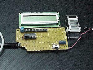
Figure 1: Prototype of Distance Meter.

This project demonstrates the use of 16×1 line LCD module to interface with Nitron 16-pin MCU, 68HC908QY4. The original idea came from one evening I went out with my son to the park near my home in Korat. The park has a nice walking way for people to exercise. I was wondering how long the distance is? I thought it would be nice if we know distance for one round.

 Electronic Distance MeterIt seemed to me that it’s quite long, but I didn’t know exactly. My son ridden bicycle while I was walking along him. I look at the bicycle wheel, and thought may be we can measure distance with the help of wheel rolling. The week before I brought a magnet from BaanMor, it was the rare earth magnet.I thought why don’t have the reed switch as the sensor and use the magnet tied to a wheel. Detection of rolling is then made by proximity effect, when the magnet close to the reed switch. This close/open reed switch contact can use to make on-off signal. I chose MCU from Motorola, a 16-pin 68HC908QY4 for counting the pulse signal produced by reed switch.

Hardware Schematic

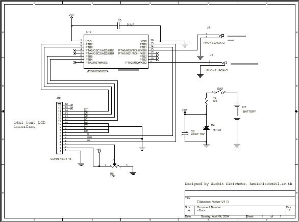
The MCU uses internal oscillator, internal reset, so we need only to supply the +VDD and VSS. I put the decoupling cap 0.1uF to VDD and VSS. Interface signals for LCD are D4-D7, RS and E. It was 4-bit interfacing, no BUSY checking. The LCD connector is 16-pin SIP socket. D0-D3 is not used, so we must tie to GND. Also R/W# was tied to GND. Since we can not check BUSY bit, so the delay routine must be used to wait LCD ready for command and data writing.

 Electronic Distance MeterThe sensor inputs are PTA2 for reed switch contact and PTA0 for 0/+5V analog input. I used small phone jack for both sensors. The analog input is optional. I haven’t got the idea what sensor should be used. The power supply is battery with simple +5.1V zener diode. You can use +9V battery or 1.5Vx3 AA battery. The circuit can run properly when the supply down to +3V. Care should be taken if you will use ADC, since the VREF is the same as VDD!


For more detail: Electronic Distance Meter

Current Project / Post can also be found using:

  • adult clip japanesse big boobs

The post Electronic Distance Meter using pic microcontroller appeared first on PIC Microcontroller.

Interfacing 16X2 LCD with PIC Microcontroller

$
0
0

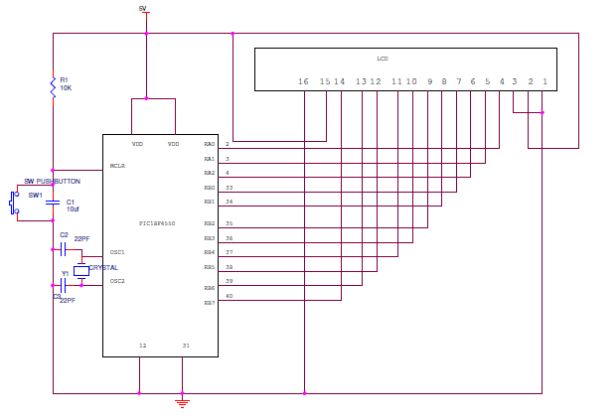
In this session we will see how to interface 16×2 LCD to PIC18F4550 microcontroller which is of family PIC18F. You can get information of 16×2 LCD in the session How to Interface 16X2 LCD with 8051 Microcontroller

Interfacing 16X2 LCD with PIC Microcontroller

Features of PIC18F4550:

  • PIC18F4550 belongs to the PIC18F family; PIC18F4550 is an 8bit microcontroller and uses RISC architecture. PIC18F4550 has 40 pins in PDIP (dual in line package) and 44 pin in TQFP (Quad flat package).
  • 32KB flash memory, 2048 bytes of SRAM (synchronous Random Access memory), EEPROM (Electrically Erasable Program Read Only Memory) of 256 bytes are embedded in the PIC18F4550.
  • It has 35 I/O pins for interfacing and communication with other peripherals, 13channel of 10bit analog to digital converters which are used for interfacing and communicating the analog peripherals (DC motor, LDR, etc.).
  • It has 2 CCP and 1 ECCP module that is enhanced capture and compare module which is mainly used for modulation and waveform generation functions. CCP module is of 16bit register works as 16 capture bit register, 16 compare bit register, and PWM and duty cycle register.
  • PIC18F4550 has SPI (serial peripheral interface) and i2c (inter integrated circuit) for master and slave modes. It has SPP (Streaming Parallel Port) for USB streaming transfer.
  • PIC18F4550 is embedded with 4 timer modules (timer0 to timer3), 2 comparator modules and 3 external interrupt. It has Dual Oscillator options allow microcontroller and USB module to run at different clock speeds. It can operate in 2.0V to 5.5V

16X2 LCD Interfacing PIC Microcontroller – Circuit Explanation:

The resistor R1 is used for giving the contrast to the LCD. The crystal oscillator of 12 MHz is connected to the OSC1 and OSC2 pins of Pic microcontroller PIC18F4550 for system clock. The capacitor C2 and C3 will act filters to the crystal oscillator. You can use different ports or pins for interfacing the LCD before going to different ports please check the data sheet whether the pins for general purpose or they are special function pins.

Programming PIC for Interfacing 16X2 LCD:

Interfacing LCD to PIC is not different from interfacing to 8051. The basic concept and gist of the programming is almost same. Visit the following link for more information http://www.electronicshub.org/interfacing-16×2-lcd-8051/.

Only the pins, registers and architecture using for interfacing will be different. When we look at the program, functions like initialization, sending data to the LCD will be almost same.

In the pic programming also for initializing the LCD the R/W pin should be low for writing the data, Enable pins should be high and register select pin (RS) should be high for writing the data. For sending a command the RS should be low, R/W pin should be low and enable pin should be high.

Initializing the LCD function:

lcdcmd(0×38);//Configure the LCD in 8-bit mode,2 line and 5×7 font
lcdcmd(0x0C);// Display On and Cursor Off
lcdcmd(0×01);// Clear display screen
lcdcmd(0×06);// Increment cursor
lcdcmd(0×80);// Set cursor position to 1st line,1st column

Sending command to the LC:
  • rs=0;    Register select pin is low.
  • rw=0;  Read/write Pin is also for writing the command to the LCD.
  • en=1;enable pin is high.


For more detail: Interfacing 16X2 LCD with PIC Microcontroller

The post Interfacing 16X2 LCD with PIC Microcontroller appeared first on PIC Microcontroller.

Very Accurate LC Meter based on PIC16F628A

$
0
0

About Accurate LC Meter

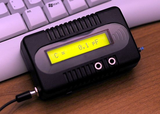
This is one of the most accurate and simplest LC inductance / capacitance Meters that one can find, yet one that you can easily build yourself. This LC Meter allows to measure incredibly small inductances starting from 10nH to 1000nH, 1uH to 1000uH, 1mH to 100mH and capacitance from 0.1pF up to 900nF. LC Meter’s circuit uses an auto ranging system so that way you do not need to spend time selecting ranges manually. Another neat function is reset switch that will reset the initial inductance / capacitance, making sure that the final readings of the LC Meter are as accurate as possible.Very Accurate LC Meter based on PIC16F628A

Special Edition Accurate LC Meter Kit

Special Edition LC Meter Kit includes top notch high precision components that are only found in premium quality kits. It includes high quality double-sided printed circuit board (PCB) with red solder mask and pre-soldered tracks for easier soldering, LCD display with yellow-green LED backlight, programmed PIC16F628A microcontroller chip, high precision capacitors and inductor, 1% Metal Film resistors, Machined IC Sockets, gold plated header pins, LCD header connectors and all the other components that are needed to build a premium quality kit. Thanks to the use of LCD connectors LCD display can be detached from the main PCB board at any time even after the kit has been assembled. Special Edition Accurate LC Meter is designed for professionals that require unprecedented measurement accuracy and offers great value at low cost.

How does LC Meter Work?

To be able to determine the value of an unknown inductor / capacitor we can use the frequency formula given below.

Note that there are three variables that we can work with; f, L and C (f represents a frequency, L inductance and C capacitance). If we know the values of the two variables we may calculate the value of the third variable.

Lets say we want to determine the value of an unknown inductor with X inductance. We plug X inductance into the formula and we also use value of a known capacitor. Using this data we can calculate the frequency. Once we know the frequency we can use the power of the algebra and rewrite the above formula to solve for L (inductance). This time we will use the calculated frequency and a value of a known capacitor to calculate the inductance.

Isn’t this amazing? We just calculated the value of unknown inductor, and we may use the same technique to solve for the unknown capacitance and even frequency.

Applying the Theory to LC Meter’s Hardware

< width=”791″>

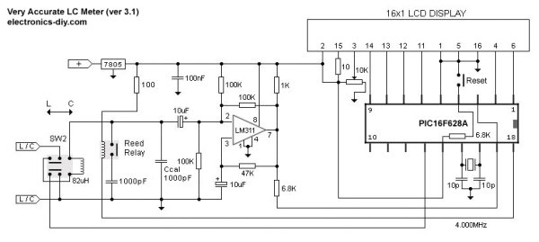
Now let’s use the above theory and apply it to electronics. The LC Meter uses a popular LM311 IC that that functions as a frequency generator and this is exactly what we need. If we want to calculate the value of an unknown inductor we use a known Ccal 1000pF capacitor and the value of an unknown inductor. LM311 will generate a frequency that we can measure with a frequency meter. Once we have this information we can use the frequency formula to calculate the inductance.

The same thing can be done for calculating the value of a unknown capacitor. This time we don’t know the value a capacitor so instead we use the value of a known inductor to calculate the frequency. Once we have that information we apply the formula to determine the capacitance.

All this sounds great, however if we want to determine the value of a lot of inductors / capacitors then this may become a very time consuming process. Sure, we can write a computer program to do all these calculations, but what if we don’t have an access to a computer or a frequency meter?

That’s were PIC16F628A microcontroller comes handy. PIC16F628A is like a small computer that can execute HEX programs that are written using an assembly language. PIC16F628A is a very flexible microcontroller because it has PINs which can be configured as inputs and outputs. Besides that, PIC16F628A IC requires very minimal number of external components like 4.000MHz crystal / resonator and a few resistors. Before PIC16F628A microcontroller can be used it has to be programmed with a HEX code which has to be sent from the computer. All Accurate LC Meter kits already come with microcontroller that is already programmed and ready to be used.

In the next step we use the frequency generated by LM311 IC and pass it on to PIC 16F628A’s PIN 17. We designate this PIN as an input, as well as all other PINs that are directly connected to switches. User can use these inputs to tell the microcontroller to execute specified set of instructions or perform calculations.

Once the microcontroller will calculate the unknown inductance or capacitance it will use PINs that are designated as outputs and pass the results onto the 16 character green backlighted LCD display.Very Accurate LC Meter based on PIC16F628A schematich

LC Meter’s Switches

< width=”9″ height=”82″>

< width=”791″>

Reset Switch – Resets capacitance / inductance readings
SW2 Switch – Capacitance / Inductance switch
Grounding PIC16F628A PIN12 displays the initial frequency of the LM311 oscillator which should be around 550KHz. This is usefull for testing LM311 oscillator.

For more detail: Very Accurate LC Meter based on PIC16F628A

Current Project / Post can also be found using:

  • lcd pic project

The post Very Accurate LC Meter based on PIC16F628A appeared first on PIC Microcontroller.

Schematics and C code for a 0-5V PIC LCD Volt Meter. using pic microcontoller

$
0
0

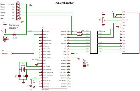
This PIC LCD volt meter project uses a PIC micro and an HD44870 LCD display. The analogue input is taken directly to the analogue input pin of the microcontroller without any other processing.

Specification

Voltage range 0V – 5V
Input signal level TTL
Maximum input impedance 2k5

The LCD volt meter uses the microcontroller power supplies as reference voltages and so it is not likely to be very accurate (e.g. a 7805 5V regulator has an accuracy of 4%).

Schematics and C code for a 0-5V PIC LCD Volt Meter.To improve accuracy add a voltage reference and feed the reference voltage to the Vref input on the PIC which is into RA3 ( change the control register values in the ADC to use the Vref). This project simply provides a quick and easy way of measuring volts without circuit complexity.

The project mainly shows how to control and setup the software to read an analogue value from the first analogue port RA0.

Note when designing using the analogue inputs its a good idea to start from AN0 as there is only a limited set of ways that more analogue ports can be selected for use (see the chip data sheet – analogue inputs).

Compiler Mikroelectronika MikroC Compiler Free!
Target 16F877A (retargetable to other PICs that have Analogue input AN0).
Software level Easy.
Software notes Using fixed point long instead of floating point.
Hardware level Easy.
Hardware notes LCD will work with LVP (if PGM pin is pulled high).
Project version 1.01
Project files Enter your details to get the Download Link
and get the microcontroller newsletter:

(Note: Your email is safe it will never be sold or rented).
You will get All the C source code and hex file.

Note: Check your email for the project code download link.

Schematics and C code for a 0-5V PIC LCD Volt Meter.PIC lcd volt meter Hardware

You can use any PIC microcontroller that has an ADC and enough memory to hold the program.

The LED is pulsed after every ADC acquisition to indicate that the processor is alive – so you can tell if the software is active.

You can program the PIC in circuit through the ICSP connector.

For more detail: Schematics and C code for a 0-5V PIC LCD Volt Meter.

The post Schematics and C code for a 0-5V PIC LCD Volt Meter. using pic microcontoller appeared first on PIC Microcontroller.

Relay Timer with PIC16F628

$
0
0
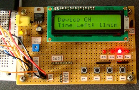
Here is 0 to 99 minutes relay timer using PIC16F628 microcontroller and 16 character LCD display. The microcontroller is PIC16F628A running at 4.0 MHz clock using an external crystal. An HD44780 based 16×2 character LCD is the main display unit of the project where you can watch and set the timer duration using tact switch inputs.Relay Timer with PIC16F628 There are three tact switches connected to RB0 (Start/Stop), RB1 (Unit), and RB2 (Ten) pins. You can select the timer interval from 0-99 min using Unit and Ten minute switches. The Start/Stop switch is for toggling the timer ON and OFF. When the timer gets ON, a logic high signal appears on the RA3 pin, which can be used to switch on a Relay. The circuit diagram of this project is described below.
Relay Timer with PIC16F628

Build Accurate LC Meter and start making your own coils and inductors. This LC Meter allows to measure incredibly small inductances making it perfect tool for making all types of RF coils. Relay Timer with PIC16F628 schematichLC Meter can measure inductances starting from 10nH – 1000nH, 1uH – 1000uH, 1mH – 100mH and capacitances from 0.1pF up to 900nF. The circuit includes an auto ranging and reset function to make sure the readings are as accurate as possible .

For more detail: Relay Timer with PIC16F628

The post Relay Timer with PIC16F628 appeared first on PIC Microcontroller.

Digital DCF77 clock with LCD and gong using PIC16F628A

$
0
0

Always the right time and date with DCF77

This project make use of a PIC16F628(A) and a DCF77 receiver from Conrad (Orderno. 64 11 38)

Optional there is a possibility to connect an electronic gong on it.
Click for information about DCF77 on the link underneath:

The working from the DCF77 time signal

Connect the output from the DCF77 module with PORTB.0 (pin 6).
The pull-up resistor on the DCF77 output isn’t necessary because PORTB.0 internal pull-up is enabled.

Digital DCF77 clock

Every second is on PORTA.1 (pin 18) a pulse from 0.5 second.
This signal isn’t necessary for anything, but maybe you want to connect a LED on it, so that these wil blink every second, or a piezo buzzer, so that the clock ticks as an analog clock.

PORTA.0 (pin 17) is the daylight-saving time (DST) pin and is high when it is summer.
For the LCD’s 2×20 and 2×24 is it possible to print a W or S on the LCD in winter/summertime.

When connect PORTA.6 (pin 15) to +5V, the clock stays in 24 hours notation and if is choosen for 12 hours notation (AM/PM) then connect this pin with GND.

Use a HD44780 (or compatible) device for the LC-Display.
Download the .HEX file which belongs to the used LCD size.


When switching the power on, the PIC waits till it get a signal from the DCF77 module (receiver).


When searching does take more than 45 seconds, the message “No signal” follows.
The PIC stays searching until it have a decent timesignal reception.


When there is a signal found, it search to the begin from a new minute, this will take maximum 1 minute.
The timebar gives the left time.
If the whole timebar is full, then there is no startsecond found and the message “No signal” appears.


When the startsecond is found, the bits are gonna filled with time and date.
This takes exactly one minute.
If the whole timebar is full, the actual time and date is complete.


From now the day, time and date can be read.


If PORTA.6 (pin 15) is connected to GND the clock stays in 12 hours (AM/PM) notation.
The W stays for Wintertime (S for Summertime, DST).
There is a .HEX file with W / S and a .HEX file without this indication.


When the reception becomes worse or disappears, then also follows the message “No signal”.
The PIC still keeps trying to find the actual time back when the reception is good (again).


The basis
If only the time and date must be read from LCD without any fuss then build the circuit from scheme 1.
Adjust the contrast from the LCD with P1.


For more detail: Digital DCF77 clock with LCD and gong using PIC16F628A

Current Project / Post can also be found using:

  • pic 18f452 c rogram lcd
  • Real time clock in pic18f452 projects using mp lab

The post Digital DCF77 clock with LCD and gong using PIC16F628A appeared first on PIC Microcontroller.


Microcontroller Controlled Metal Detector Projects

$
0
0

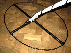
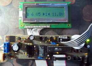
Result of displays in the form of two scales, which are estimated to judge the material goal.In addition, the screen is small scale level of response and the current supply voltage. PIC18F252 The program is intended for controller PIC18F252.The controller PIC16F873 (A) to this version can not be used. This is more demanding to resources controller. 252nd compatible controller on “pins” with 873 – m and can be programmed by the same programmer. The program workable only with korzinochnymi reels! R21 For this firmware needed zakorotit resistor R21 (in the old version of the scheme). In this version the appointment of buttons changed to readMicrocontroller Controlled Metal Detector Projects

PIC16F873A Metal Detector Clone PI

PIC16F873A Metal Detector ClonePI-2

ClonePI-2 is a further development of the project ClonePI). The main objectives in the design – to get discrimination metals

PIC16F873A Metal Detector ClonePI

ClonePI AVR is a so new simplistic solution pulse metal ClonePI)

# Use pic16f873a controller available from Atmel.
# Instead of using an external ADC ADC internal controller.
To get the same sensitivity as to the external ADC, is used oversampling.
# Use taktirovanie of internal RC-generator controller. Microcontroller Controlled Metal Detector Projects schematich

PIC16F873A PI Metal Detector ClonePI-W

Instead of LCD used LED display. Cut down on administration, leaving only the most necessary. Take into account some errors in previous versions.

MICRICHIP, ATMEL AVR Microcontroller Controlled Metal Detector Projects all files download: microcontroller-controlled-metal-detector-projects.RAR alternative link2 alternative link3


For more detail: Microcontroller Controlled Metal Detector Projects

The post Microcontroller Controlled Metal Detector Projects appeared first on PIC Microcontroller.

PIC16F877 LCD code and Proteus simulation

$
0
0

This PIC16F877 microcontroller tutorial provides very detailed and comprehensive LCD[1] code.

PIC16F877 LCD

Using PIC16 simulator (Proteus) you can verify this LCD code and change it according to your needs. This code is written in C language using MPLAB with HI-TECH C compiler. You can download this code from the ‘Downloads‘ section at the bottom of this page.

It is assumed that you know how to blink an LED with PIC16F877 microcontroller. If you don’t then please read this page first, before proceeding with this article.

The following diagram (made in Proteus) shows the PIC microcontroller circuit diagram.

PIC16F877 LCD schematic

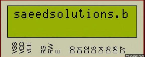
In the above figure, RB0 pin is being used as RS pin for LCD. RB1 pin is used as RW pin, RB2 pin is used as Enable pin and RB4 to RB7 pins are used as Data bus for the LCD. When code starts running then ‘saeedsolutions.blogspot.com‘ is displayed on the first line of LCD first. Also, on the second line in the end, two custom characters are also displayed (Downward arrow and Upward arrow). Then whole screen starts to scroll towards left. Following animation shows the result of simulating the code in Proteus.

Code

The code for the main function is shown below.

Downloads

LCD interfacing code using PIC16F877 was compiled in MPLAB v8.85 with HI-TECH C v9.83 compiler and simulation was made in Proteus v7.10. To download code and Proteus simulation click here.


For more detail: PIC16F877 LCD code and Proteus simulation

The post PIC16F877 LCD code and Proteus simulation appeared first on PIC Microcontroller.

How to interface LCD with PIC18F4550 Microcontroller

$
0
0

The character LCDs are the most commonly used display modules. These LCDs are used to display text using alphanumeric and special characters of font 5×7/5×10. For basic working and operations of a character LCD, refer LCD interfacing with 8051. Here PIC18F4550 has been used to display a single character on a 16×2 character LCD.

For basic details and operations of character LCD, refer LCD interfacing with 8051. Here LCD has been interfaced in 8-bit mode* with data pins (D0-D7) connected to PortB of PIC18F4550. The LCD control pins RS, R/W and EN are connected to PortA pins RA0, RA1 and RA2 respectively.

 interface LCD with PIC18F4550
*Character LCD can also be interfaced by using only 4 data lines. Refer LCD interfacing in 4-bit mode.
Programming Steps:
Before displaying anything on LCD, it needs to be configured with proper instructions. The following programming steps explain the procedure of configuring the LCD and display a character on it.
Step 1: Initialize the LCD.
The LCD must be initialized the by following pre-defined commands of character LCD.
·         0x38, to configure the LCD for 2-line, 5×7 font and 8-bit operation mode
·         0x0C, for Display On and Cursor Off
·         0x01, to Clear Display screen
·         0x06, to increment cursor
·         0x80, to set cursor position at first block of the first line of LCD.
The above set of commands is written in lcd_ini() function of the adjoining code.
Step 2: Send the commands to LCD.
·         Send the command byte to the port connected to LCD data pins
·         RS=0, to select command register of LCD
·         RW=0, to set the LCD in writing mode
·         EN=1, a high to low pulse to latch command instruction
·         Delay of 1ms
·         EN=0
The above set of commands is written in lcdcmd(unsigned char) function.
Step 3: Send data to LCD.
·         Send data at the port which connected to LCD data pins
·         RS=1, register select to select data register of LCD
·         RW=0, this set the LCD in writing mode
·         EN=1, a high to low pulse to latch data
·         Delay of 1ms
·         EN=0
The lcddata(unsigned char) function has the above set of instructions.

The post How to interface LCD with PIC18F4550 Microcontroller appeared first on PIC Microcontroller.

A Cheap Ultrasonic Range Finder

$
0
0

HOW DOES IT WORK & CIRCUIT SCHEMATIC

Everybody knows the speed of the sound in the dry air is around 340 m/s. Send a short ultrasonic pulse at 40 Khz in the air, and try to listen to the echo. Of course you won’t hear anything, but with an ultrasonic sensor the back pulse can be detected. If you know the time of the forth & back travel of the ultrasonic wave, you know the distance, divide the distance by two and you know the range from the ultrasonic sensor to the first obstacle in front of it.

A Cheap Ultrasonic Range Finder

Here we use an ultrasonic piezzo transmitter with its receiver, they are very efficient, easy to find and quite cheap.

First, we have to send the pulse : it is easy to get a 40 Khz pulse from a PIC PWM output. You can drive an ultrasonic transmitter directly from the PIC output, but the sense range will not exceed 50 cm. Using a transistor and a resonator circuit, the ultrasonic transmitter will get around 20 volts and the sense range will be extended up to 200 cm.

Second we have to sense the echo : the piezzo receiver can provide a few dozens of millivolt, this will be enough for a PIC ADC with 4 mV resolution without extra hardware.

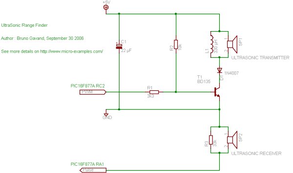
Click on schematic to enlarge

C1 is a decoupling capacitor

The PWM pulse from the RC2 pin of the PIC drives the T1 transistor base through R1 resistor

A 330 µH inductor is added in parallel to the piezzo ultrasonic transceiver, to form a LC resonnator, the D1 diode protects T1 from reverse voltage.

The ultrasonic receiver is directly connected to the RA1 pin of the PIC (ADC channel number 1), with R3 in parallel as impedance adaptator.

A Cheap Ultrasonic Range Finder schemetic

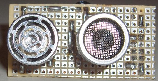
The prototype board

<- Component side

Solder side ->

Take care to align as best as possibe the transmitter with the receiver

SOURCE CODE

Here is the mikroC source code :

/*
* file         : sonar.c
* project      : Simple UltraSonic Range Finder
* author       : Bruno Gavand
* compiler     : mikroC V6.2
* date         : september 30, 2006
*
* description  :
*      This is a basic ultrasonic range finder, from 30 to 200 centimeters
*
* target device :
*      PIC16F877A with 8 Mhz crystal
*      or any PIC with at least one ADC and PWM channel
*
* configuration bits :
*      HS clock
*      no watchdog
*      no power up timer
*      no brown out
*      LVP disabled
*      data EE protect disabled
*      ICD disabled
*
* see more details and schematic on http://www.micro-examples.com/
*//********************
* MACRO DEFINITIONS
********************/
/*
* ultra sonic pulse length in microseconds
*/
#define PULSELEN        300

/*
* circular buffer size for samples averaging
*/
#define BUFSIZE 10

/*
* LCD PORT
* EasyPic2, EasyPic3 : PORTB
* EaspyPic4 : PORTD
*/
#define LCDPORT PORTD
#define LCDTRIS TRISD

/*******************
* GLOBAL VARIABLES
*******************/
unsigned char   outOfRange ;            // out of range flag : set when no echo is detected

unsigned int    buf[BUFSIZE] ;          // samples buffer
unsigned char   idx = 0 ;               // index of current sample in buffer

/*****************************************
* INTERRUPT SERVICE ROUTINE
* This ISR handles TIMER1 overflow only
*****************************************/
void    interrupt(void)
{
if(PIR1.TMR1IF)                                       // timer1 overflow ?
{
outOfRange = 1 ;                              // set out of range flag
PIR1.TMR1IF = 0 ;                             // clear interrupt flag
}
}

/************
* MAIN LOOP
************/
void    main()
{
ADCON1 = 0 ;            // enables ADC

TRISA = 0xff ;          // PORTA as inputs
PORTA = 0 ;

TRISC = 0 ;             // PORTC as outputs
PORTC = 0 ;

// TIMER1 settings
T1CON = 0b00001100 ;    // prescaler 1:1, osc. enabled, not sync, internal clk, stopped

#ifdef   LCDPORT
// init LCD
Lcd_Init(&LCDPORT) ;            // use EP2/3/4 settings
Lcd_Cmd(Lcd_CLEAR) ;            // clear display
Lcd_Cmd(Lcd_CURSOR_OFF) ;       // cursor off

Lcd_Out(1, 1, “UltraSonicRanger”) ;
Lcd_Out(2, 5, “cm”) ;
#endif


For more detail: A Cheap Ultrasonic Range Finder 

The post A Cheap Ultrasonic Range Finder appeared first on PIC Microcontroller.

Augustus’s Lab Notebook using pic microcontoller

$
0
0

Week 01

January 10, 2012 (1 hour):
Met as a team after class to discuss preliminary project proposal.

January 12, 2012 (2 hours):
Met as a team after class to finish writing preliminary project proposal.

WEEK 01 SUMMARY
Accomplishments: Submitted preliminary project proposal.
Weekly Work Total: 3 hours
Project Work Total: 3 hours

Week 02

January 17, 2012 (2 hours):
Met as a team to formulate PSSC for presentation in class on January 25th.

January 19, 2012 (3 hours):
Met as a team to finish the final project proposal.

January 20, 2012 (1 hours):
Researched Parts.

WEEK 02 SUMMARY
Accomplishments: PSSC and project proposal finalized.
Weekly Work Total: 6 hours
Project Work Total: 9 hours

Augustus's Lab Notebook

Week 03

January 22, 2012 (3 hours):
Met as a team to research parts and set up PSSC Presentation

January 23, 2012 (3 hours):
Made the PowerPoint for the presentation. Talked to TA and he suggested that writing a usb driver for XBee would not be feasible because it is really complicated. Thought of using IMUs for motion capture, but wasn’t sure if the magnetometer was needed.

January 25, 2012 (1 hours):
PSSC Presentation

January 26, 2012 (3 hours):
Met as a team to finish the PCB layout homework. Finalized on the IMU without the magnetometer.

WEEK 03 SUMMARY
Accomplishments: PSSCs Finalized, PCB layout tutorial finished
Weekly Work Total: 10 hours
Project Work Total: 19 hours

Week 04

January 29, 2012 (2 hours):
Met as a team to discuss design constraint homework. Divided parts for the homework. Worked on the wireless module design and component selection. Decided to choose XBee Series 1 due to it’s low power consumption, plus its simplicity to set up.

January 30, 2012 (2 hours):
Talk to Chuck and TA about Wireless module component selection. Chuck suggested to look at the wireless module by Microchip which was used by the HOARD Robotics team. He also suggested the XStick USB interface for XBee.

January 31, 2012 (2.5 hours):
Worked more on the design constraint homework, put together presentation for TCSP. Improved the set of PSSCs and decided to use a Atom board for the base station.

February 2, 2012 (1 hours):
Worked more on the design constraint homework. Attempted to pick a suitable micro that has enough I2C as well as SPI ports.

WEEK 04 SUMMARY
Accomplishments: Finalized the wireless module to be XBee series 1, and decided on the micro that has enough ports. Worked on the design constraint homework, and put together the TCSP Presentation. Decided to use a mother board instead of a laptop.
Weekly Work Total: 7.5 hours
Project Work Total: 26.5 hours

Week 05

February 6, 2012 (1 hours):
Met as a team to break down the packaging homework.

February 7, 2012 (2 hours):
Worked on packaging homework and put together the slides for TCSP

February 9, 2012 (1 hours):
Met as a team to break the hardware design and schematics homework. We found out that the development board for the micro we chose is obsolete. And thus we worked on picking a new micro. Harsh found a PIC micro that was suitable to our needs. It also have a lot of documentation and examples for which convenient for our development. Also discussed the possible sketch for the schematics.

February 12, 2012 (3 hours):
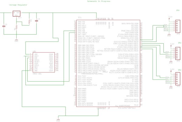
Finished the schematic for the hardware design homework. Also worked more on the writing portion of the homework.

WEEK 05 SUMMARY
Accomplishments:
Weekly Work Total: 7 hours
Project Work Total: 33.5 hours

Week 06

February 14, 2012 (2 hours):
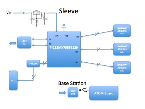
Met as team and talked about the preliminary version of the schematic, discussed possible places for decoupling capacitors and the overall structure of the power supply circuit. Made a updated block diagram.

Laid out preliminary version of the schematic, connecting all important components to the microcontroller. Presented for TCSP in class, learned that a debugging circuit is required for if we want to debug the microcontroller after we soldered it onto the PCB board. Also learned to use a voltage switch regulator instead of linear regulator to reduce power consumption.

WEEK 06 SUMMARY
Accomplishments: Laid out the preliminary schematic, including the power supply circuit, XBee, and imu interfaces. Learned in TCSP that a debugging interface is needed.
Weekly Work Total: 7 hours
Project Work Total: 40.5 hours

Week 07

Febuary 19, 2012 (1 hours):
Met as team to talk about making a more detailed schematic, and PCB design. Thought about using a LCD to display battery life and wireless signal strength. The downside of using the LCD however, is that if we choose to use a 5V LCD, then we need to somehow produce a 5V input from the 3.3V power supply.

Febuary 20, 2012 (1 hours):
Met as team to split up work for PCB design. Steve is going to implement a charge pump that will charge the 3.3V input to 5V.

Febuary 23, 2012 (1 hours):
Mike had a problem when he tried to debug the PIC32 microcontroller through the debug board. For some reaon the MPLAB could not recognize the board. Played around with the board but still couldn’t figure out why, will need to talk to Chuck or TAs about this issue

WEEK 07 SUMMARY
Accomplishments: Decided to use a charge pump to step up 3.3V input to 5V for the LCD, made custom parts library with Mike for the PCB layout.
Weekly Work Total: 6 hours
Project Work Total: 46.5 hours

Week 08

Febuary 26, 2012 (2 hours):
Started on formal design review. We broke down tasks that have to be done for the review. Found out that there are 3.3V LCDs available from Sparkfun that would fit our deisgn. In the end still decided to use the charge pump since the circuit in the schematic has already been made. Also decided to add a rocker switch to power on/off for implicity of use. Also decided to go with removable battery instead of making a charging circuit since it would be too much trouble, and we packaging design would allow us to easitly detach the battery and charge it.

Febuary 28, 2012 (1 hours):
Talked to TA about adding a bulk capacitor into our schematic. TA suggested that it should be around 50-100uF and there are one available in the lab.

Febuary 29, 2012 (5.5 hours):
Worked on the powerpoint for the deisgn review. Updated block diagram correcting pins and removing the charge pump. We have decided to use a 3.3V LCD found on Sparkfun since then we can remove the charge pump circuit, reducing power consumption and size of the pcb board. The LCD draws less 20mA current which is not a problem since our power circuit can provide up to 3A. Added a reset button onto the schematic, however there are still problems remaining with the pcb board. Thus far the part where the reset button is added is crowded and thus it is hard to route the reset button onto the board. Also there are still some traces that are not connected or have acute angles. One pin from XBee is routed incorrectly to the microcontroller and we need to find a way to route that. Also made a project timeline for the formal review.

March 1, 2012 (2 hours):
Formal Design review. Learned several points in the review. 1) add debuggin pins into the schematic and pcb. 2) Several connections traces are still loose, and there are some acute angles. 3)Someone suggested that the user of the sleeve might be left handed. We need to take that into consideration when making data calculations and displaying image. 5)Talked about possible solutions for having variable length wires. Full Schematic

WEEK 08 SUMMARY
Accomplishments: Worked on formal design review. Finalized parts for circuit, including taking out the charge pump, using a 3.3V LCD, adding a reset button to the design.
Weekly Work Total: 9.5 hours
Project Work Total: 56 hours

Augustus's Lab Notebook

Week 09

March 5, 2012 (1.5 hours):
Met as a team and broke down modules for each person to complete. Found a paper that details robot arm kinematics which should be really useful when we want to do calculations for displaying the 3D arm. The paper is called “Robot Arm Kinematics, Dynamics, and Control by C.S. George Lee”.

March 7, 2012 (2 hours):
Proof of parts briefings. Talked about how to improve the atom board’s graphic performance. Chuck said there’s not that much we can do except turning off unnecessary applications. Suggested that we should present two vesions on the final demo. One on the atom board and one on a PC. Also learned that we need to add surface aread for heat sink, and use a 16V electrolytic 100uF capacitor. Below is the PCB layout made by Harsh

March 8, 2012 (2 hours):Read more on the robot arm kinematics paper. Found we could use rotation matrices for poistion calculation. Given the rotational and translational motion data from the sensors, we could build a 4X4 rotation matrics that would give us the final position of each joints.

WEEK 09 SUMMARY
Accomplishments: Found a robot arm kinematics paper that would make it convinient for us to calculate arm position, using a rotation matrix build from sensor data. Learned how to improve the pcb board during proof of parts review, including increasing the size of the heat sink and adding bulk capacitors.
Weekly Work Total: 5.5 hours
Project Work Total: 61.5 hours

Week 10

March 12, 2012 :
Spring Break

WEEK 10 SUMMARY
Accomplishments:
Weekly Work Total: 0 hours
Project Work Total: 61.5 hours

For more detail: Augustus’s Lab Notebook

Current Project / Post can also be found using:

  • programme pic 18f lcd
  • lcd 16×2 craete project use mplap ide
  • lcd 16×2 create sample project mplab ide
  • lcd 16×2 project use mplap ide

The post Augustus’s Lab Notebook using pic microcontoller appeared first on PIC Microcontroller.

PIC16F877 based controllable digital clock using LCD display (Code+Proteus simulation)

$
0
0

This PIC16F877 microcontroller tutorial answers the question,
” How to implement a controllable digital clock using PIC16F877 ? “

PIC16F877 based controllable digital clock using LCD display

Using PIC16 simulator (Proteus) you can verify this digital clock code and change it according to your needs. Using three push buttons (As shown in figure below) you can adjust time as you desire. This code is written in C language using MPLAB with HI-TECH C compiler. You can download this code from the ‘Downloads‘ section at the bottom of this page.

In this article, it is assumed that you know,

  • How to make a simple digital clock using PIC16F877. If you don’t then please read this page.
  • How to interface LCD with PIC16F877 microcontroller. If you don’t then please read this page.
  • How to configure timer0 of PIC16F877 microcontroller.  If you don’t then please read this page.

The following diagram (made in Proteus) shows the PIC microcontroller circuit diagram.

PIC16F877 based controllable digital clock using LCD display schematic

The above figure was taken after setting time to 07:58:54, timer0 is used as the base for digital clock generation. Timer0 is used here to generate 1msec interrupts. After every 1msec a global variable named msCounter increments. When msCounter reaches a value of 1000 then another global variable named secCounter increments and this process repeats itself. Similarly, when secCounter reaches 60, then  minCounter increments. And when minCounter reaches 60 then hrCounter increments. This process continues until hrCounter reaches 24 then all of these variables reset their values. LCD is updated with the new values of hrCounterminCounter and secCounter after every second.

You can set time using three push buttons attached on RE0, RE1 and RE2 pins (As shown in the above figure). By pressing ‘Set Time‘ button one time, code enters in configuration state. Hours value starts to blink and you can modify it using Up and Down buttons. Pressing Up button increments the value and pressing Down button decrements the value. When you are done setting Hours value, press ‘Set Time‘ button again, then Minutes value will start to blink and you can adjust this value using Up and Down buttons. Similarly, after setting Minutes value, you can press ‘Set Time‘ button again, then Seconds value will start to blink and you can adjust this value using Up and Down buttons. When you are done adjusting the time, then press ‘Set Time‘ button for the last time and this clock will start to work normally.
A crystal of 4MHz value is used in this circuit, which makes this PIC16F877 run at a speed of 1MIPS (Million of instructions per second).

Code

The main function code is shown below.

Downloads

Controllable digital clock display code using PIC16F877 was compiled in MPLAB v8.85 with HI-TECH C v9.83 compiler and simulation was made in Proteus v7.10. To download code and Proteus simulation click here.


For more detail: PIC16F877 based controllable digital clock using LCD display (Code+Proteus simulation)

Current Project / Post can also be found using:

  • digital calender & time using rtc & microcontroller mini project
  • membuat digital timer delay relay with PIC16F648A

The post PIC16F877 based controllable digital clock using LCD display (Code+Proteus simulation) appeared first on PIC Microcontroller.

Interface single and Dual IR Infrared sensor with PIC18F4550 and LCD

$
0
0

In this another tutorial on sensors  for beginners, we are going to interface single and multiple Infrared IR sensors with Arduino Uno development board, working simultaneously and have the status displayed either on an ( 4X16 LCD ) LCD module (jhd162a) or an LED. We are going to cover three chapters in single tutorial in simple step by step fashion. The purpose of this tutorial is to serve the basics for beginners with Sensor interface on Arduino for being able to use these concepts and to develop various other sensor based applications (robotics, Automation Projects etc.). We will use the same Object Detection Proximity IR Sensor Module that we made in our precedent tutorial. In our previous Proximity Sensor tutorials we have learned how to interface IR sensor with various other microcontrollers such as PIC18F4550 and 18F2550; However, today we are going to learn how to interface the same infrared sensor with the famous Arduino Uno board.Interface single and Dual IR Infrared sensor with Arduino and LCD

To begin easy, first we are going to interface a Single IR sensor for sensing the distance and read the value of the sensor using an Arduino board and have status displayed on a LED. On the next level we are going to do same with two IR sensors working simultaneously. At last we will interface (add) an LCD (Liquid Crystal Display) and have the status of both the Infrared sensors displayed on a 4X16 LCD Display unit. The Concepts for Reading the IR sensor is still same as explained in previous lessons, the only difference is the Arduino board.

Tutorials

Requirements

PIC18F4550
– Infrared IR sensor Module
– JHD162a 4X16 LCD
– Resistors
– LEDS

Infrared IR Sensor Module

We will use the IR Infrared Sensor Circuit module that we made in our previous project, which is an inexpensive (Low Cost)  sensor circuit module. You can find the schematic and PCB design in my previous post. There are three pins in the Schematic – Two pins for providing the input voltage and GND, and the third pin from the IR module is the IR control pin. This Control Pin from the IR sensor Module will be interfaced to the Arduino for reading the value from sensor. We will use two identical copies of the sensor for our tutorial.

Single Infrared IR Sensor Interface to PIC18F4550Microcontroller

Chapter1

As mentioned before we are going to start easy,hence here we going to interface just one infrared sensor circuit with Arduino, the source code is pretty much self-explanatory. Like every microcontroller, we need to define pins either as input or output. We have configured Pin 13 as output, and pin 9 as input for taking input from sensor. The Result of sensor will reflect on the LED connected on pin13 which is configured as output. The source code can be tweaked easily to display the result on serial monitor too.

We are going to leave pin 0 to Pin 7 on Arduino Uno untouched for using it with LCD operation in future. Make the Circuit ready according to the schematics below to proceed further. Arduino will draw power from USB hence there is no need to interface external power supply as long as the board is connected with USB cable.Interface single and Dual IR Infrared sensor with Arduino and LCD schematich

Schematic (Single Sensor Interface)

USE and GND and +5V pins on the arduino to power the IR sensors. Make the necessary wiring acording to the schamatic given below.

NOTE: The operation is quiet similar to that of interfacing a simple switch to Arduino or any microcontroller, But here you don’t need to ground the input pin (pull-down) with a resister. In Arduino pin13 by default is interfaced with an Onboard led for displaying status. We can use that one onboard led or you can interface an Extra led on Pin 13 to have the Status displayed.


For more detail: Interface single and Dual IR Infrared sensor with PIC18F4550 and LCD

Current Project / Post can also be found using:

  • gas detector using pic 18f microcontroller project
  • project on LCD
  • Small Project on transducer

The post Interface single and Dual IR Infrared sensor with PIC18F4550 and LCD appeared first on PIC Microcontroller.


PIC18F4550 – LCD display jhd162a ( 2×16) Interface

$
0
0

Project : Display control on a LCD (jhd162a )

Requirements
jhd162a LCD
PIC18f4550
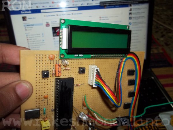
Here in this project the running display of the screen is been controlled by a PIC18f4550 board which is interfaced to jdh162a lcd. jdh162a lcd is very easily available in any electronic shops. The Video below shows LCD interface with my USB board .PIC18F4550  LCD display jhd162a  216 Interface

Watch this Video Carefully. The Display on the Screen is controlled by a small software written on C# , which communicates through a USB cable to pic18f4550 which is interfaced to jhd162 a LCD. The dispay commands from Computer finnally is Displayed on jhd162a LCD with Some set of LCD string commands (c#). The base firmware loaded on PIC18f4550 which is written by MPLAB IDE and HI-TECH C Compiler.

Computer > USB > pic18f4550 > JHD16 2a LCD Display

Uploaded by RON RONEY on Jan 20, 2012 on youtube

Its a small demonstration of a jhd 162a lcd, jhd 16 2a is a small 2×16 character lcd ,with PIC18F4550 microcontroller .

JDH 162a

jhd162a is 16 pin LCD display which can be easy interface to projects to provide a cool display. Its cheap and and can be found in any Electronic shop very easily.

Mor information you can refer DATA Sheet For jhd162a .PIC18F4550  LCD display jhd162a  216 Interface schematic

-In indian Money it costs around 200 Rs. (3-4 $) .

-2×16 Charater Display

Thanks For watching The Firmware and C# software with Complete Coding details with Step by step Tutorial will be posted here very soon.

For more detail: PIC18F4550 – LCD display jhd162a ( 2×16) Interface

Current Project / Post can also be found using:

  • dcf77 pic 16f876
  • PIC LCD projects in asm
  • pic microcontroller lcd projects

The post PIC18F4550 – LCD display jhd162a ( 2×16) Interface appeared first on PIC Microcontroller.

Introducing the BOLT PIC18F2550 Microcontroller Board using pic microcontoller

$
0
0

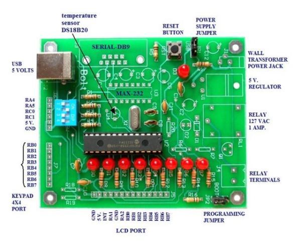
The BOLT microcontroller board utilizes the Microchip 18F2550 with built in USB capabilities. Utilizing a 2k ‘boot loader’ this leaves a great deal of flash RAM for C programming using MPLAB and the C18 compiler. The BOLT board comes in two versions. LITE which has the 18F2550, 8 LEDs for PORTB, four switches and a USB 2.0 port connection to a PC. Operating with a 20 mHz crystal, by use of internal multipliers operates at 48 mHz.

Introducing the BOLT PIC18F2550 Microcontroller BoardThe full version has additional components including a relay, DS18B20 temperature sensor, RS232, etc. I went with the LITE version and added my own 90 degree header pins. The idea was to port over my Arduino projects to PIC C and learn how to program PICs. The BOLT comes with a lot of working examples in both assembly and C to gives the novice a place to start.

The system is powerful and inexpensive. With the LITE version at $15 which includes the 18F2550 it requires no external PIC programmer just a USB cable. This is right in the price range of an Arduino at three times the speed. While I’m using the 28-pin version, there’s a 40-pin version with more I/O.

In comparison to Arduino I’d advise against using a PIC starting out without some electronics and C programming knowledge. One will also need to understand and setup MPLAB and understand the C18 compiler libraries which can be very valuable. While having a steeper learning curve than Arduino, it has greater versatility and potential.

The website for the BOLT is at http://www.puntoflotante.net/BOLT-SYSTEM.htm in Mexico. Be warned some of the notes in the examples are in Spanish but are fairly self-explanatory. I’m including ZIP files with the BOLT template which includes linker file and several H files for ADC, serial, and One-Wire. I also include most of the examples.

The PIC18F2550 has 32k of flash (2k used by boot loader), 2k of SRAM, 256 bytes of EEPROM, 24 I/O pins, 10 10-bit ADC channels, 2 PWM, USART, USB 2.0, etc. This is a RISC processor with 75 instructions and is ‘optimized’ for a C compiler.

Below are a listing of my recent projects ported over mostly from my Arduino projects and some extra. I have my own code and H files depending on what hardware one wants to attach to the system. My LCD routines are for use with my serial 74164 LCD project from Arduino.
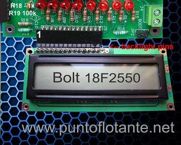
Introducing the BOLT PIC18F2550 Microcontroller BoardSee Connect Arduino to LCD Display with 74164 Shift Register

The board can use a common HD44780 directly connected to BOLT as shown above. Two resistors must be added: R18 is 1k and R19 is 100k. Notice the two backlight pins are disconnected. If one’s display requires a backlight (mine did being blue) then solder a jumper from pin 15 (anode) to +5 volts (or pin 2) and pin 16 (cathode or K) to GND or pin 1.

In my case I soldered in a 5k potentiometer replacing R18/R19 to better adjust contrast.

There are two ways to connect the LCD display to BOLT either parallel as shown above or with my serial LCD project ported over from my Arduino project.


For more detail: Introducing the BOLT PIC18F2550 Microcontroller Board

Current Project / Post can also be found using:

  • ultrasonic sensir interfacing to pic16f887 programming in hi tech c

The post Introducing the BOLT PIC18F2550 Microcontroller Board using pic microcontoller appeared first on PIC Microcontroller.

2-wire LCD interface using PIC16CF84

$
0
0

Alphanumeric LCD displays have become very popular for microcontroller applications because they can add a lot to a project in a variety of different ways. A text message giving the user instructions as well as feedback can make the application seem much more “professional” and easy to use. I like to use LCD’s to help debug applications, with breakpoints set to display variable and I/O conditions and they are a lot cheaper than using a microcontroller emulator. To top it off, surplus LCD’s can be found for a dollar or less.2-wire LCD interface using PIC16CF84

The most popular LCD interface is the Hitachi 44780 based LCD controller chip which provides a fairly easy to work with interface and low power consumption. The major drawback of the interface is the perceived complexity of working with the interface. This perception has been promoted by the lack of good (i.e. well translated) and accurate datasheets and web site information.

Often the biggest stumbling block to using alphanumeric LCD displays is the number of pins required to control them. For the Hitachi 44780, twelve pins are required from the microcontroller to interface to the display for it to work in eight bit mode. For many smaller microcontrollers, twelve pins are not available or will be better served in the application. To be fair, this can be reduced to six by using the 44780’s “Four Bit” mode, but this can still be more than acceptable for most applications.

A popular solution that only requires one pin from the microcontroller to the LCD is the use of “Serial LCD Interfaces”  to the data and signals necessary for the Hitachi 44780 controllers.

Many of these products (such as the SLI-OEM) are excellent and can provide useful product interface and debugging information. The only drawback to them is the need for properly timed NRZ serial data which may be difficult or even impossible to guarantee in some applications.

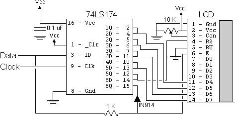
In this case, different approaches have to be made. The most popular one is to use synchronous serial data (requiring a “clock” and “data”) pin to load a serial-in/parallel-out shift register with the data bits and “R/S” pin information. The “E” Strobe Pin is driven directly by the microcontroller to latch in the data from the LCD. This is shown in the diagram below:

The project presented in this article is an enhancement of this circuit. By combining the shift register’s “Data Line” with the most significant bit of the shift register, the “E” Strobe can be implemented without resorting to a separate line for the function. The 1 K resistor and diode act as an “AND” gate. A schematic of the circuit is shown below.

The operation of the resistor/diode “AND” gate may not be immediately obvious. When the shift register bit is low, the diode pulls the connection to the “E” pin low. When the shift register bit is high, the diode will not cause any current flow from the connection at the “E” pin to the shift register. The resistor from “Data” to the “E” pin is a current limiting resistor. When the shift register bit is low and the data bit is high, then the current through the resistor will be limited to 5 mA (for a 5 Volt logic application). At the “Data” side of the resistor, the voltage will still be high, even though the diode is pulling the “E” pin low.2-wire LCD interface using PIC16CF84 schematic

When both the “Data” line and the shift register bit are high, the “E” pin will be high. The “AND” circuit could be a TTL two input AND gate (such as a 7408), if you have an extra one available for your application. When I originally created this circuit, I used the same two transistor and two resistor circuit that I used for the 89C2051 emulator in “Programming and Customizing the 8051 Microcontroller”. I saw this “AND” equivalent circuit in an old copy of “Electronics Now” and found that it worked well in this application.

To load the shift register, it first has to be cleared to ensure that the “E” will not be strobed to the LCD inadvertently. This is done by first shifting in six “0”s to make sure that while the correct data is being loaded into the shift register, no “high” voltage level is passed to the “E” pin of the LCD.

Once this is done, the data can be shifted in. The diagram below shows how the shift register is initially cleared and then loaded with the data to be strobed (using “E”) into the LCD:

For more detail: 2-wire LCD interface using PIC16CF84

Current Project / Post can also be found using:

  • pic32 microcontroler profetional rtos projects

The post 2-wire LCD interface using PIC16CF84 appeared first on PIC Microcontroller.

Using Digole 12864ZW LCD with PIC18F

$
0
0

Digole 12864ZW is a 128×64 pixels graphic LCD that can be found at attractive prices and this is why it started appearing in projects across the web. It is based on ST7920 chip which is not so well known and to me it wasn’t the easiest to work with.’

The documentation for this display can be found here. You can find a couple of examples on how to use this display and some attempts on making a library and most of this information is for interfacing with arduino. For PIC interfacing i couldn’t find much info.

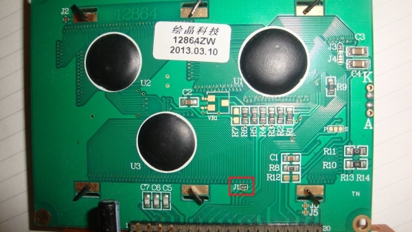
The module has a 20 pin connection, each described below. Vout i havent used and left it unconnected. For contrast you can use V0 (pin 3) by connecting it to Vdd through a 10k variable resistor. However to get it to work you will need to enable jumper J1 from the back of the module as in figure 1.

Using Digole 12864ZW LCD with PIC18F

Pin # Function
1 Vss
2 Vdd
3 V0
4 RS
5 RW
6 EN
7 DB0
8 DB1
9 DB2
10 DB3
11 DB4
12 DB5
13 DB6
14 DB7
15 PSB
16 NC
17 RST
18 VOUT
19 BLA
20 BLK

As per the datasheet the display can be used in many ways and this is a strong feature. I used it the traditional way 8 bits parallel. For this, PSB pin must be connected to Vdd, i also connected RST pin to Vdd as i will reset the display in software. The rest of the connections are the same as with any 16×2 alphanumeric displays.

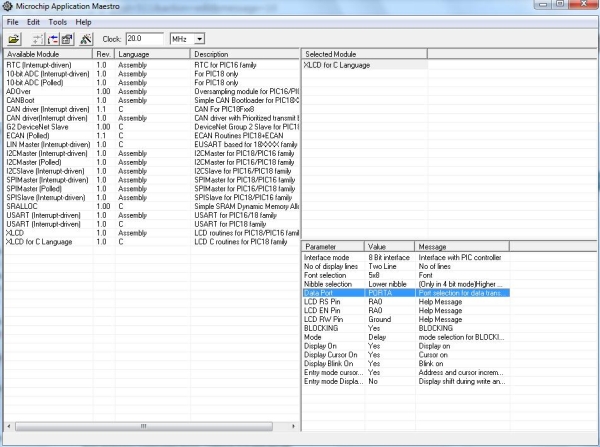
Microchip XLCD library is a great starting point to using the Digole 12864ZW with a PIC microcontroller. I used Application Maestro to set up the library. As mentioned we will use 8 bits interface in delay mode. Set the ports and pins and the rest doesn’t really matter.

Once done pressing Ctrl+G will generate the library files to be included in your project. You will need the XLCD.h, XLCD.c and XLCD.def. Now this Digole display can run in text mode with this library with major issues.To get to each line though you will need to go to specific addresses.

To use the LCD in graphic mode we will need to change the XLCDinit function in XLCD.c file.

void XLCDInit(void){_vXLCDreg=1;

XLCD_DATAPORT_TRIS  = 0x00; 
XLCD_DATAPORT = 0;
XLCD_RSPIN_TRIS =0;                         
XLCD_ENPIN_TRIS =0;
XLCD_RWPIN_TRIS =0;
XLCD_RSPIN  =0;                             
XLCD_ENPIN  =0;
XLCD_RWPIN=0;                               
XLCDDelay15ms(); 
XLCD_DATAPORT   = 0b00110000;   
XLCDDelay4ms();
XLCD_DATAPORT   = 0b00110000;   
XLCDDelay4ms(); 
XLCDCommand(0x0C); 
XLCDDelaylcd();   
XLCDCommand(0x01); 
XLCDDelay15ms();  
XLCDCommand(0x06); 
XLCDDelaylcd();
XLCDCommand(0x34); 
XLCDDelay15ms();    
XLCDCommand(0x36); 
XLCDDelay15ms(); 

_vXLCDreg=0;return;}

Using Digole 12864ZW LCD with PIC18FThe other two functions we will use from the XLCD library are XLCDCommand and XLCDPut, which are used to pass a command to the display and a value respectively. Using these functions you don’t have to worry about controlling RS , RW and EN.

After calling the XLCDinit() function in main() you have now setup the display in graphic mode. To start drawing you need first 2 XLCDCommand instructions that set the pixel address and then 2 XLCDPut instructions to draw the pixels.

In figure 3 you can see the address map of Digole 12864ZW in the operating mode described above. It can be observed the horizontally you cannot address pixels individually but in groups of 16 and values you can write in groups of 8. The 1st byte represents the byte in the first XLCDPut instruction and the 2nd byte the value in the 2nd instruction. You cannot make 1 byte to start at the middle of the address location. We have 8 addresses of 16 pixels each horizontally 8×16=128 pixels and 64 lines =>128×64 resolution.


For more detail: Using Digole 12864ZW LCD with PIC18F

The post Using Digole 12864ZW LCD with PIC18F appeared first on PIC Microcontroller.

Mechanically scanned laser display using PIC17F877

$
0
0

Abstract

This application is a very cheap solution for displaying text messages on a solid or semi-opaque surface by using a laser beam. The main goal was to verify the possibility to build a simple and cheap display for displaying large text.

The basic idea was to use only one light source (a laser beam) and mirrors to scan the display surface.

laser display

So, the main parts used to build the display are:

    • a laser diode from a key-chain pointer
    • a cassette player motor
    • an ingenious “head” with mirrors
    • a PIC17F877 board with the associated circuitry
    • a power supply

The head is an octagonal prism, with a small mirror on each lateral face. Each mirror is mounted with different angles, giving different reflection angles for the laser beam.

The basics of this design is similar with television principles: the laser beam is reflected by the mirrors placed on each face of the octagonal head creating a raster. This raster is modulated by turning on/off the laser beam. The Microcontroller board receives one pulse per rotation from the rotational speed sensor and calculates very precisely the moment for turning on/off the beam.

There is a RTC (real time clock) and a temperature sensor block which is optional. The purpose of this block is to provide the corresponding data to the microcontroller for displaying. But, because the main goal was to test the possibility to build the display, I didn’t assembled the optional components.


For more detail: Mechanically scanned laser display using PIC17F877

The post Mechanically scanned laser display using PIC17F877 appeared first on PIC Microcontroller.

Viewing all 253 articles
Browse latest View live


<script src="https://jsc.adskeeper.com/r/s/rssing.com.1596347.js" async> </script>