Quantcast
Channel: LCD Projects - PIC Microcontroller
Viewing all 253 articles
Browse latest View live

Traffic Message Channel receiver using PIC18F8722

$
0
0

Main roads traffic status and incident report and display.


Technical specifications:

  • Dual display: colour road map (left) and detailed text messages (right) both with LED backlight.
  • Up to 120 TMC messages are stored in memory.
  • Auto/manual TMC message scrolling.
  • GPS position locator/follower optional.
  • Map navigation with  mouse sensor and/or micro joystick.
  • Map zoom 10km to 80km (in 10km steps)
  • City and area presets preconfigured.
  • High quality NXP TEF6901AH chip used for best performance.
  • Integrated RDS/RBDS radio data demodulator.
  • All parts will be available at our shop.

  • TMC countries to be supported: Belgium , Netherlands, Germany , France , Sweden  and more to come…
  • This product will be ported to a smaller OLED OmniBoard project (054 – LiveQ) and will be available as a KIT (PCB + parts) from our online shop.

Traffic Message Channel receiver

Free schematics and source code available for download. Last update: August 15, 2008.

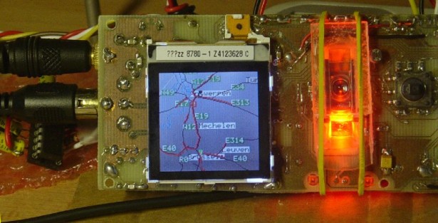
Dual display, mouse touchpad and joystick.

Power in (9V..12V AC/DC)

The tuner TEF6901AH, microcontroller PIC18F8722, USB controller, Memory card and power supply  are located on the backside.

  • Audio output and antenna input.
  • Nokia 6610 Colour LCD (128×128) with road map.
  • Mouse sensor (red) for touchpad navigation.
  • Micro joystick for controls and navigation.


For more detail:  Traffic Message Channel receiver using PIC18F8722

Current Project / Post can also be found using:

  • car security using pic microcontroller and sensor(pdf)

The post Traffic Message Channel receiver using PIC18F8722 appeared first on PIC Microcontroller.


Lab 4: Interfacing a character LCD using PIC16F688

$
0
0

Description

HD44780 based LCD displays are very popular among hobbyists because they are cheap and they can display characters. Besides they are very easy to interface with microcontrollers and most of the present day high-level compilers have in-built library routines for them. Today, we will see how to interface an HD44780 based character LCD to a PIC16F688 microcontroller. The interface requires 6 I/O lines of the PIC16F688 microcontroller: 4 data lines and 2 control lines. A blinking test message, “Welcome to Embedded-Lab.com”, will be displayed on the LCD screen.

character LCD

Required Theory

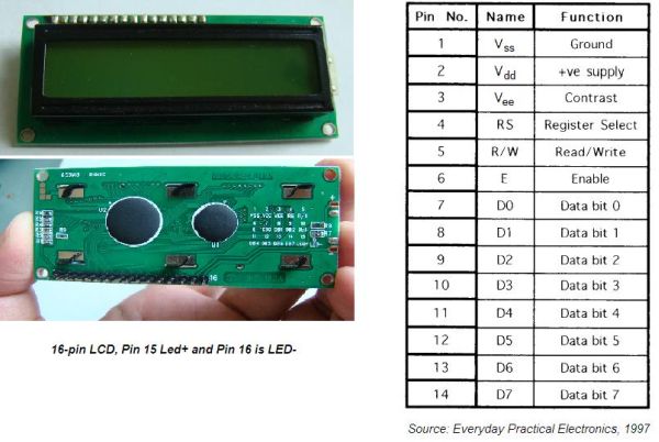
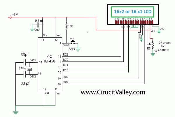
All HD44780 based character LCD displays are connected through 14 pins: 8 data pins (D0-D7), 3 control pins (RS, E, R/W), and three power lines (Vdd, Vss, Vee). Some LCDs have LED backlight feature that helps to read the data on the display during low illumination conditions. So they have two additional connections (LED+ and LED-), making altogether 16 pin. A 16-pin LCD module with its pin diagraam is shown below.

Control pins
The control pin RS determines if the data transfer between the LCD module and an external microcontroller are actual character data or command/status. When the microcontroller needs to send commands to LCD or to read the LCD status, it must be pulled low. Similarly, this must be pulled high if character data is to be sent to and from the LCD module.

The direction of data transfer is controlled by the R/W pin. If it is pulled Low, the commands or character data is written to the LCD module. And, when it is pulled high, the character data or status information from the LCD registers is read. Here, we will use one way data transfer, i.e., from microcontroller to LCD module, so the R/W pin will be grounded permanently.

The enable pin (E) initiates the actual data transfer. When writing to the LCD display, the data is transferred only on the high to low transition of the E pin.

Power supply pins
Although most of the LCD module data sheets recommend +5V d.c. supply for operation, some LCDs may work well for a wider range (3.0 to 5.5 V). The Vdd pin should be connected to the positive power supply and Vss to ground. Pin 3 is Vee, which is used to adjust the contrast of the display. In most of the cases, this pin is connected to a voltage between 0 and 2V by using a preset potentiometer.

Data pins
Pins 7 to 14 are data lines (D0-D7). Data transfer to and from the display can be achieved either in 8-bit or 4-bit mode. The 8-bit mode uses all eight data lines to transfer a byte, whereas, in a 4-bit mode, a byte is transferred as two 4-bit nibbles. In the later case, only the upper 4 data lines (D4-D7) are used. This technique is beneficial as this saves 4 input/output pins of microcontroller. We will use the 4-bit mode.

For further details on LCDs, I recommend to read these two articles first from Everyday Practical Electronics magazine : How to use intelligent LCDs Part 1, and Part 2.

Circuit Diagram

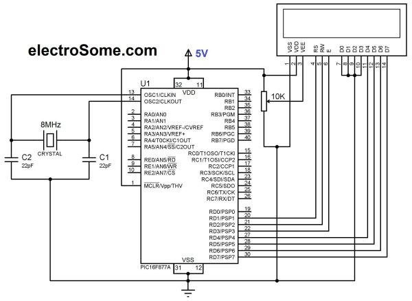
Data transfer between the MCU and the LCD module will occur in the 4-bit mode. The R/W pin (5) of the LCD module is permanently grounded as there won’t be any data read from the LCD module. RC0-RC3 serves the 4-bit data lines (D4-D7, pins 11-14) of the LCD module. Control lines, RS and E, are connected to RC4 and RC5. Thus, altogether 6 I/O pins of the PIC16F688 microcontrollers are used by the LCD module. The contrast adjustment is done with a 5K potentiometer as shown below. If your LCD module has backlight LED, use a 68Ω resistance in series with the pin 15 or 16 to limit the current through the LED. The detail of the circuit diagram is shown below.


For more detail: Lab 4: Interfacing a character LCD using PIC16F688

The post Lab 4: Interfacing a character LCD using PIC16F688 appeared first on PIC Microcontroller.

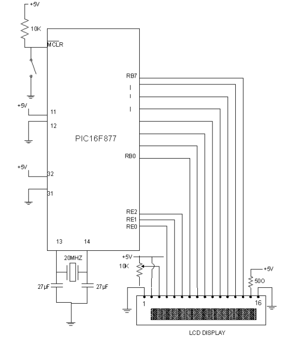
Lecture 43 : Interfacing PIC16F877 Microcontroller with an LCD

$
0
0
Aim

To interface LCD (Displaytech 162A) with PIC16F877microcontroller and to display “IITK” in the Liquid Crystal Display (LCD).

Components/Softwares
  1. MPLAB IDE (PIC microcontrollers simulator)
  2. PIC BURNER 3 with software to load the code
  3. LCD (Displaytech 162A)
  4. Computer System with Windows operating system and RS 232 cable
  5. PIC16F877 Microcontroller

Lecture 43  Interfacing PIC16F877 Microcontroller with an LCD

  1. +5V D.C Power Supply
  2. Resistors – 10K Ω-1,50Ω-1
  3. Capacitors – 27 µ F-2
  4. Potentiometers – 10K Ω -1
  5. 20MHz Crystal oscillator
  6. SPST switches -1
Procedure
  1. Write the assembly code in MPLAB IDE simulator , compile it and check for errors
  2. Once the code was error free, run it and check the output in the simulator.
  3. After checking the code in the simulator, load the code (in .HEX format) into PIC16F877 microcontroller using PIC BURNER3.
  4. Make connections as shown in the circuit diagram.
  5. Switch on the power supply and observe “IITK” displayed in the LCD.

Liquid Crystal Display (LCD-Displaytech 162A )LCD Displaytech 162A consists of a LCD panel, a controller IC (KS0070B) and a back light LED. The LCD module consists of total 16 pins in which, 2 are for power supply, 2 pins for Backlight LED, one pin for contrast adjustment, 3 pins are for control signals and 8 pins are data pins. In order to display any data, we need to do certain initiations. The following are the main three steps in displaying any data in the LCD display.

Lecture 43  Interfacing PIC16F877 Microcontroller with an LCD Schematic

  1. Initializing LCD by sequence of instructions
  2. Executing commands depending on our settings in the LCD
  3. Writing data into the DRAM locations of LCD in the Standard Character Pattern of LCD

For doing above steps, refer the manual for LCD and follow the instructions and timing diagrams strictly.
MPLABIDEMPLABIDE is a free software which can be downloaded from the website www.microchip.com
Working with MPLABIDE :
MPLABIDE is a simulator for PIC microcontrollers to write and edit the code in assembly language, compile it and also to run the code. Output can be verified using simulator.


For more detail: Lecture 43  Interfacing PIC16F877 Microcontroller with an LCD

The post Lecture 43 : Interfacing PIC16F877 Microcontroller with an LCD appeared first on PIC Microcontroller.

HD44780 16×2 Char LCD Interfacing with microcontroller

$
0
0

Project Description:-

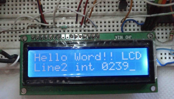
In this project we are going to learn various things about this chip set and displaying text on this LCD. The HD44780 16×2 char LCD screen Use 8bit and 4 bit parallel interface with backlight.

This Primary Objective in this project are:-

1.  Displaying  “Hello Word!! LCD ” message on the scree.
2.   Interfacing The LCD to the Microcontroller Using 8bit  Mode and 4 Bit Mode.
3.  Generating and Displaying Custom Char on the LCD Screen. clik here for custom char

Operation 

as i have mentioned  before this type of lcd are connected to microcontroller using parallel 8bit or 4bit lines.
using 8 bit method is quite simple but take 8 lines (for data or command)+ 3 control signal total 11 line , i guess few small microcontrollers don’t even have that much of I/O lines ,so in 4 bit mode total 7 lines (sometimes 6 ) are required .  in this tutorial i will show you with both of the methods .

HD44780 16x2 Char LCD Interfacing with microcontroller Pin description

PIN NUMBER SYMBOL FUNCTION
1 Vss GND
2 Vdd  + 3V or + 5V
3 Vo Contrast Adjustment
4  RS H/L Register Select Signal
5 R/W H/L Read/Write Signal
6 E  H → L Enable Signal
7  DB0 H/L Data Bus Line
8  DB1 H/L Data Bus Line
9  DB2 H/L Data Bus Line
10  DB3 H/L Data Bus Line
11  DB4 H/L Data Bus Line
12  DB5 H/L Data Bus Line
13  DB6 H/L Data Bus Line
14  DB7 H/L Data Bus Line
15 A/Vee + 3.5V for LED/Negative Voltage Output
16 K K Power Supply for B/L (OV)

in 8 bit mode all the Data line DB0 to DB7 are being used for transferring the the data to lcd but in 4-bit mode only 4 line form DB4 to DB7 are being used to transfer the  8 bit wide data in two peaces one after another .

we can’t display any data on the lcd until all the required internal command register of the lcd are not being properly initialized.
to know every thing about this lcd controller .. you can go through it’s data sheet
click here to download HD44780 data sheet
so now we will learn how to initialize the lcd.

LCD Commands

Clear Display

clear  and place the cursor in the first position (address 0). The bit I / D to 1 by default.

RS R / W DB7 DB6 DB5 DB4 DB3 DB2 DB1 DB0
0 0 0 0 0 0 0 0 0 1

Return the cursor to Home

Place the cursor in the home position (address 0) and make the display starts to move from its original position. The contents of the RAM display data (DD RAM) remains unchanged. The address of the RAM for display data (DD RAM) is set to 0.

RS R / W DB7 DB6 DB5 DB4 DB3 DB2 DB1 DB0
0 0 0 0 0 0 0 0 1 X

Entry Mode in Set

Set cursor moving direction and specify that the display moves to the next position of the screen or not. These operations are performed during reading or writing of the DD RAM or CG RAM. To view usually set bit S = 0.

RS R / W DB7 DB6 DB5 DB4 DB3 DB2 DB1 DB0
0 0 0 0 0 0 0 1 I / D S

Display ON / OFF Control

Turn on or off by turning ON / OFF both the LCD (D) as the cursor (C) and whether or not this last flash (B).

RS R / W DB7 DB6 DB5 DB4 DB3 DB2 DB1 DB0
0 0 0 0 0 0 1 D C B

Cursor or Display Shift

Move the cursor to move the LCD without changing the memory contents of the display data DD RAM.

RS R / W DB7 DB6 DB5 DB4 DB3 DB2 DB1 DB0
0 0 0 0 0 1 S / C R / L X X

HD44780 16x2 Char LCD Interfacing with microcontroller SchematicFunction Set

Set the size of interface with the data bus (DL), number of lines in the LCD (N) and character type (F).

RS R / W DB7 DB6 DB5 DB4 DB3 DB2 DB1 DB0
0 0 0 0 1 DL N F X X

Set the CG RAM Address

The LCD module defined in addition to all the ASCII character set allows the user to define 4 or 8 characters. The composition of these characters is saved to a CG RAM memory called up to 64 bytes. Each user defined character consists of 16 or 8 bytes that are stored in successive positions of the CG RAM.

Using this instruction sets the CG RAM memory address from which the bytes will be stored that define a character. Running this command all the data that is subsequently read or write this memory made from CG RAM.


For more detail: HD44780 16×2 Char LCD Interfacing with microcontroller 

Current Project / Post can also be found using:

  • lcd dislay pic
  • pic24f i2c master with usb example

The post HD44780 16×2 Char LCD Interfacing with microcontroller appeared first on PIC Microcontroller.

1. Serial interfacing LCD with Pic Microcontroller

$
0
0
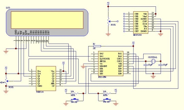
Parallel interfacing LCD with MCU at least need 6 I/O pins (4 bit mode) and maximun can up to 
11 I/O pins (8 bit mode). The I/O pin can be cut down to 3 pin by serial iterfacing using shift 
register. They were few shift register can be used such as 74HC164, 74HC595, CD4094 and any 
compatible 8 bit shift register. Before you attempt to do serial interfacing, it is good 
pratice to familiar with parallel interfacing. You can find many reference from internet. 
Following diagram show the serial interfacing Hitachi compatible 2 X 16 LCD modules with 
Pic16F84 or Pic16F628 MCU.

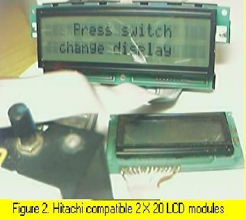
The Hitachi compatible 2 X 16 LCD modules drive by Pic16F84 MCU show on figure 1. The Hitachi compatible 2 X 20 LCD modules (optrex) drive by Pic16F84 MCU show on figure 2. When using this optrex 2 X 20 LCD modules, the Vref (pin 3 at LCD) need around -4.5v to -5.5V supply. The source code/hex file for Pic16f84 download here: F84SLCD.zip. The source code/hex file for Pic16f628 download here: 628SLCD.zip.

1. Serial interfacing LCD with Pic MicrocontrollerMore LCD reference can find here:

  1. www.myke.com
  2. www.eio.com
  3. www.repairfaq.org
  4. www.iaehv.nl
  5. www.shellyinc.com

2. Software SPI interfacing ADC with Pic16F84/Pic16F628

Communication with the MCP3028 ADC chip is done using a simple serial interface compatible
with the SPI protocol. The Pic16f84 or Pic16f628 didn't had hardware SPI peripheral. However, 
software implemeted SPI protocol can be done to communicate with 12 bit MCP3028 ADC device. 
The example of this communication shown as following circuit diagram. The ADC result shown
on LCD with hex value (conversion from binary code). Press the push button (pin 6, RB0/INT)
to select the ADC channel (8 channel from CH0 to CH7). Then, connect the potention meter to
the channel and turn it. You will see the hex value change accordingly. The SPI communication 
protocol need 4 line for interfacing. Using software implemeted SPI protocol enable 
communication with more than one ADC device. 
The hex file for Pic16f84 download here: F84S_L.zip.
The hex file for Pic16f628 download here: 628S_L.zip.

3. Simple multi channel digital voltmeter

The circuit diagram same as above 12 bit ADC interfacing. The only different is the source code
which the binary code has been change to ASCII code with decimen number. This need some math 
fuction such as divide function and floating point. The math fuction for assembler code can 
find from Microchip Website www.microchip.com. You can also find some documen of math fuction 
from www.piclist.com or use C compiler such as Piclite for PIC16f8X/c8x series, cc5x c, 
pacific c and so on. The following hex file are use Microchip Math Library (assembler code) for 
this simple multi channel digital voltmeter device (using 16 bit for calculation). The maximum 
hex value for the ADC channel is FFF equal to decimel number 4095. This will display on the LCD 
as 5.11 volt.

Download hex file for Pic16F84 here: F84dec.zip.
Download hex file for Pic16F628 here: 628dec.zip.
*Tip on source code migration from Pic16f8X series to Pic16f62X series*
  1. If using PORTA pins as interfacing I/O, you need to define/set the I/O fuction for PIC16f628. Generally, the initial PORTA setting as following for I/O fuction: clrf PORTA movlw 0x07 ;turn comparators off and movwf CMCON ;enable pins for I/O functions Note: Ensure the above setting done at Bank 0. The above setting especially important if you want to migrate the source code from Pic16f8X series to Pic16f62X series.
  2. Always refer to data memory MAP (on Pic datasheet) to ensure that the general purpose register used not out of range when migrate one type of MCU to another type of MCU. As example, general purpose register for Pic16f84 was 0x00c to 0x04f (at bank 0). For Pic16f628 was 0x020 to 0x07f (at bank 0), 0x0a0 to 0x0ef (at bank 1) and 0x120 to 0x14f (at bank 2). It is better to define the address follow sequence.If out of range, you can re-define it easly.
  3. When Using bit 4 (RB4) of PORT B of Pic16F62X series as a output pin, ensure that the MCU not programmed at low voltage program mode (see Microchip datsheet) if not it will set as Schmitt Trigger input and independence of TRISB regeister I/O direction setting.

Serial interfacing LCD with Pic Microcontroller SchematicStepper motor controller

The stepper motor driver circuit shown as following
The opto-isolator are important which prevent destroy of MCU by the feeback voltage from 
power transistor. Two adjust-able voltage regulator used to adjust the running voltage and 
stopping/holding voltage of the stepper motor. The running voltage on by
the step pulse input which also signal to rotate the motor. The simple source
code using interrupt method to change the step sequence (one wave) download here:
F628_stepper for Pic16F628.
Simple mathematics algorithm able to drive more complicate step sequence (such as half step)
even for half_step 5phase stepper. 
Another stepper motor circuit for X-Y table project click here:X-Y table project

More stepper motor information refer to:

1)www.cs.uiowa.edu
2)www.ams2000.com

5). 24 segments LED display module

The numerical LED display module was widely used in display application. The most common numerical LED display module consists of either 8 segmented or 
16 segmented LED units. However, this type of display module only limited to display numerical character (0 to 9) and a few type of alphabet character. 
Most of alphabet word message displayed using alphanumerical LED modules with dot matrix arrangement.
The 24 segments LED display module designed in such a way that enable it to display  alphabet (A to Z) and numerical (0 to 9) character. 
This will able it to display most of word message using A to Z alphabet and numerical character when combine a few units of this module. 
The display controlling method also more simple than the dot matrix type of alphanumerical LED module.


For more detail: 1. Serial interfacing LCD with Pic Microcontroller

Current Project / Post can also be found using:

  • lcd interfacing with pic microcontroller 16f 84 pdf
  • pic microcontroller projects lcd
  • pic 16f84a lcd project circuit
  • pic16f628a clock lcd asm

The post 1. Serial interfacing LCD with Pic Microcontroller appeared first on PIC Microcontroller.

Pic Projects With Schematics And Source Code

$
0
0
Circuit-Zone.com – Electronic Projects, Electronic – Project list | pic microcontroller, »circuit digital clock using pic16f628a microcontroller schematics » they act only ones – right then, when it´s really necessary » how to burn or program pic. Electronics projects circuits, Electroschematics.com: over 1050 top electronics projects and electronic circuits with photos, datasheets and easy to read schematics plus how it works and how to. Lcd projects – pic microcontroller, Build a simple 9600 baud 8n1 lcd terminal for debugging and testing the projects having rs232c output. introduction this lcd terminal provide two modes of operation.

Pic Projects With Schematics And Source Code Digital Thermometer Circuit Project

Pic-based applications westford microsystems, Westford microsystems westford, vermont, usa projects using microchip pic® mcus written in and featuring ccs c code last modified 01/15/2015 “but when the kindness.The microcontroller projects resources., “looking for the best microcontroller projects and resources?” here you can find microcontroller projects and tutorials designed by me a “professional.Microcontroller based circuits / projects tutorials, Home > electronic tutorials > quick reference links to some useful circuits > microcontroller based circuits / projects / tutorials: quick reference links for some.Circuit-zone. – electronic projects, electronic, Rotary encoders are very versatile input devices for microcontroller projects. they are like potentiometers expect of digital nature and unlike analogue.

Pic Projects With Schematics And Source Code Schematic

System Sequence Diagram Example

Microchip pic micros – source sample code, C sample code for pic micros and hi-tech c. sample projects for the microchip pic micro series of microcontrollers, including the pic12x, pic16x, pic18x, pic24x, and.Project list | pic microcontroller, »circuit digital clock using pic16f628a microcontroller schematics » they act only ones – right then, when it´s really necessary » how to burn or program pic.

For more detail: Pic Projects With Schematics And Source Code

Current Project / Post can also be found using:

  • lcd pic projecs

The post Pic Projects With Schematics And Source Code appeared first on PIC Microcontroller.

d.i.y. Handheld Multichannel Analyzer (MCA) based on 16F877 PIC Microcontroller and LCD

$
0
0

Some time ago I was developing a medical instrument which required histogramming, which got me in the mood to retake my own PIC MCA project(http://home.comcast.net/~prutchi/index_files/scint.htm ).

d.i.y. Handheld Multichannel Analyzer (MCA) based on 16F877 PIC Microcontroller and LCD

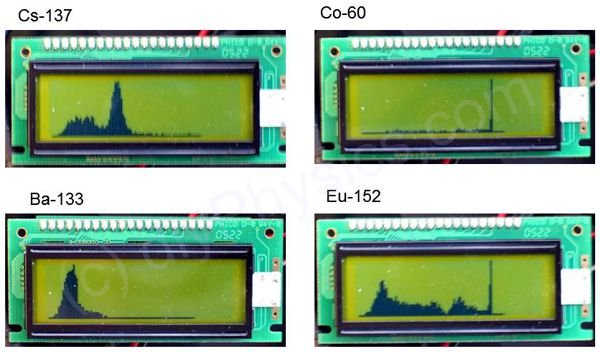
I used the variable RAM in the microcontroller (16F877), so I limited the number of channels to 95 and let the histogram run until some channel reaches 240 counts (the highest 8-bit number that yields an integer when divided by 8 which is also divisible by the 30 pixel height of the LCD).

d.i.y. Handheld Multichannel Analyzer (MCA) based on 16F877 PIC Microcontroller and LCD

The firmware then displays the spectrum as a bar with a maximum height of 30 pixels for each one of the 95 channels.

Click here for complete how-to construction instructions in pdf format.

Click here for a pdf of the schematic diagram for the front-end of the MCA


For more detail: d.i.y. Handheld Multichannel Analyzer (MCA) based on 16F877 PIC Microcontroller and LCD

The post d.i.y. Handheld Multichannel Analyzer (MCA) based on 16F877 PIC Microcontroller and LCD appeared first on PIC Microcontroller.

PIC Microcontroller Based Electronic Lock

$
0
0

Security is a prime concern in our day-today life. Everyone wants to be as much secure as possible. An access control for doors forms a vital link in a security chain. The microcontroller based digital lock for Doors is an access control system that allows only authorized persons to access a restricted area.

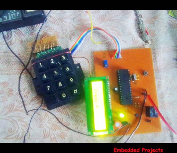
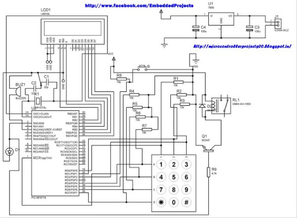
PIC Microcontroller Based Electronic LockAn electronic lock or digital lock is a device which has an electronic control assembly attached to it. They are provided with an access control system. This system allows the user to unlock the device with a password. The password is entered by making use of a keypad.

The user can also set his password to ensure better protection. The major components include a Keypad, LCD and the controller PIC16F877A. This article describes the making of an electronic code lock using the 16F877A microcontroller.

The system is fully controlled by the 8 bit microcontroller 16F877A which has a 8Kbytes of ROM for the program memory. The password is stored in the EPROM so that we can change it at any time. The system has a Keypad by which the password can be entered through it. When the entered password equals with the password stored in the memory then the relay gets on and so that the door is opened.

PIC Microcontroller Based Electronic Lock schematic

The code is built in a modular style to allow a user to find ways to modify  project. In start the D Lock programs loads with a default code of “2345” format is *2345# which can be enter to unlock the door, the code cam be change by entering the master code in the format *23455#new 4 digit code.  In this program i only display the result on LCD and lock will be  placed at   PORTA bit 0 where i put led for simulation.

A 4×3 matrix keypad and a 16×2 LCD have been used here. Keypad and LCD are very commonly used input & output devices, respectively. The password is stored in the system EEPROM.


For more detail: PIC Microcontroller Based Electronic Lock

The post PIC Microcontroller Based Electronic Lock appeared first on PIC Microcontroller.


PIC16F877A (with LCD) not working

$
0
0

I have designed a PIC18F877A micro controller project to read temperature from an LM35 using ADC, display it on an LCD and transmit it to a serial port.

When the program starts, sometimes it shows a startup message – sometimes it doesn’t display anything.

PIC16F877A (with LCD) not workingAlso, the serial port connection is not working. Can anyone help – am I missing something? Are there any ground connections missing?
My code:
#include
#device adc=10
#fuses HS,NOWDT,NOPROTECT,NOLVP
#use delay(clock=20000000)
#use rs232 (baud=9600,rcv=PIN_C7, xmit=PIN_C6)
#include
float value;
float temp;
float temp2;
float temp3;
float temp4;
float temp5[14];
float count[14];
int c;
void main(void)

PIC16F877A (with LCD) not working schematic{//setup_adc_ports( ALL_ANALOG );//Initialize and Configure ADC
//setup_adc(ADC_CLOCK_INTERNAL );
while(1)
{
lcd_init();
lcd_gotoxy (1,1);
delay_ms(1000);
printf(lcd_putc,” WELCOME TO\n Micro Tech Sol.”);
delay_ms(3000);
lcd_gotoxy (1,1);
printf(lcd_putc,” Fuel Monitoring \n PROJECT “);
delay_ms(3000);}}


For more detail: PIC16F877A (with LCD) not working

Current Project / Post can also be found using:

  • pic 18f452 lcd program pdf
  • Digital Clock Project with 8051 Using LCD pdf
  • pic microcontroller dallas lt temperature measurement
  • Project name of temperature measurement

The post PIC16F877A (with LCD) not working appeared first on PIC Microcontroller.

Up-Down counter on 16*2 LCD using 8051 microcontroller

$
0
0

DESCRIPTION

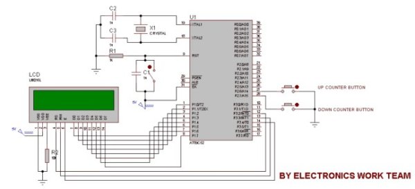
In this circuit 16*2 lcd IS used to show the value of count using 8051 microcontroller. The maximum value of count is 99 because. In this circuit we are using 8051-microcontroller, 16*2 lcd, 2 switches for up counting button & down counting button. Data pins of LCD are connected to P1 port of the 8051 microcontroller. UP counter button is connected with P2.6 and down counter button is connected with P2.7.Whenever the UP counter button is pressed the counter increments by one and when the down counter button is pressed it gets reduced by one.

Up-Down counter on 162 LCD using 8051-Microcontroller-Projects

PROJECT CODE

#include< reg51.h >

sfr lcddata=0x90; //LCD DATA PINS
sbit rs=P3^2;
sbit rw=P3^3;
sbit en=P3^4;
sbit g=P2^6;
sbit h=P2^7;

int m=0;
int a,b;
unsigned char n[10]={0x30,0x31,0x32,0x33,0x34,0x35,0x36,0x37,0x38,0x39};

void delay(unsigned char b)
{
unsigned char a;
for(b;b>0;b–)
{
for(a=500;a>0;a–);
}
}

void command(unsigned char dost)
{
lcddata=dost;
en=1;
rs=0;
rw=0;
delay(5);
en=0;
}

void lcddisplaydata(unsigned char n)
{
lcddata=n;
en=1;
rs=1;
rw=0;
delay(50);
en=0;
}

void main()
{
P2=0xFF;
command(0x38);
command(0x0C);
while(1)
{
if(g==0)
{
if(m==99)
{
command(0x80);
lcddisplaydata(n[9]);
command(0x81);
lcddisplaydata(n[9]);
}
else
{
m=m+1;
a=m/10;
{
command(0x80);
lcddisplaydata(n[a]);
}
b=m%10;
{
command(0x81);
lcddisplaydata(n[b]);
}
while(g==0);
}
}

Up-Down counter on 162 LCD using 8051-Microcontroller schematic

if(h==0)
{
if(m==0)
{
command(0x80);
lcddisplaydata(n[0]);
command(0x81);
lcddisplaydata(n[0]);
}
else
{
m=m-1;
a=m/10;
{
command(0x80);
lcddisplaydata(n[a]);
}
b=m%10;
{
command(0x81);
lcddisplaydata(n[b]);
}
while(h==0);
}
}
}
}


For more detail: Up-Down counter on 16*2 LCD using 8051 microcontroller

The post Up-Down counter on 16*2 LCD using 8051 microcontroller appeared first on PIC Microcontroller.

How to display text on 16×2 LCD using PIC18F4550 Microcontroller

$
0
0

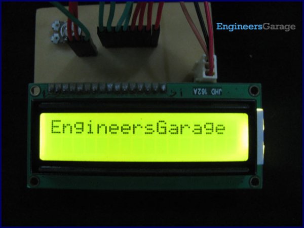
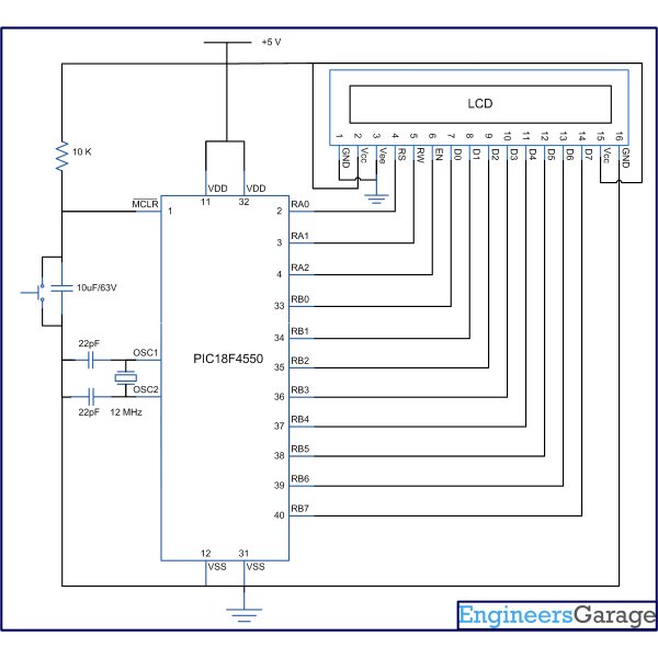
Several automated and semi-automated devices require a message to be displayed in order to indicate their working status. In continuation to LCD interfacing with PIC18F4550, this article explains how to display a message or string on a 16×2 character LCD.

How to display text on 16x2 LCD using PIC18F4550 MicrocontrollerProgramming steps:

·         Configure the LCD.
·         Store a string in a character array.
unsigned char data[20]=“EngineersGarage”;
·         Run a loop till the loop counter encounters the null character ‘\0’ of the string.
·         Use lcddata() function to send individual character values of the string to be displayed on LCD.

Code:

while(data[i]!=’\0′)
{        lcddata(data[i]);
i++;        Delay_ms(300);    }

// Program to display text on 16x2 LCD using PIC18F4550 Microcontroller

// Configuration bits
/* _CPUDIV_OSC1_PLL2_1L,  // Divide clock by 2
   _FOSC_HS_1H,           // Select High Speed (HS) oscillator
   _WDT_OFF_2H,           // Watchdog Timer off
   MCLRE_ON_3H            // Master Clear on
*/

//LCD Control pins
#define rs LATA.F0
#define rw LATA.F1
#define en LATA.F2

//LCD Data pins
#define lcdport LATB

void lcd_ini();
void lcdcmd(unsigned char);
void lcddata(unsigned char);
unsigned char data[20]="EngineersGarage";
unsigned int i=0;
How to display text on 16x2 LCD using PIC18F4550 Microcontrollervoid main(void)
{
	TRISA=0;		// Configure Port A as output port
	LATA=0;
	TRISB=0;		// Configure Port B as output port
	LATB=0;
	lcd_ini();		// LCD initialization
	while(data[i]!='\0')
	{		lcddata(data[i]);	// Call lcddata function to send characters
					// one by one from "data" array
		i++;		Delay_ms(300);
	}}void lcd_ini()
{	lcdcmd(0x38);		// Configure the LCD in 8-bit mode, 2 line and 5x7 font
	lcdcmd(0x0C);		// Display On and Cursor Off
	lcdcmd(0x01);		// Clear display screen
	lcdcmd(0x06);		// Increment cursor
	lcdcmd(0x80);		// Set cursor position to 1st line, 1st column}

void lcdcmd(unsigned char cmdout)
{	lcdport=cmdout;		//Send command to lcdport=PORTB
	rs=0;						
	rw=0;
	en=1;
	Delay_ms(10);
	en=0;


For more detail: How to display text on 16×2 LCD using PIC18F4550 Microcontroller

The post How to display text on 16×2 LCD using PIC18F4550 Microcontroller appeared first on PIC Microcontroller.

Interfacing LCD with PIC Microcontroller – CCS C

$
0
0

In this tutorial we will see How to interface a 16×2 character LCD Module with PIC 16F877A Microcontroller using CCS C Compiler. 16×2 character LCD is a very commonly used LCD module in electronic projects and products. 16×2 means it can display 2 rows of 16 characters. It is a very basic and low cost module. Its other variants such as 16×1, 20×4 are available in the market. In these displays each character is displayed using 5×8 or 5×10 dot matrix. These LCDs commonly uses HD44780 compliant controllers for their operation.

Interface between a microcontroller and LCD can be 4-bit or 8-bit. The difference between 4-bit and 8-bit is how data are send to the LCD. To write an 8-bit character to the LCD module in 8-bit mode, ASCII data is send through the data lines DB0- DB7 and data strobe is given through the E line.

Interfacing LCD with PIC Microcontroller – CCS CBut 4-bit mode uses only 4 data lines. In this mode the 8-bit ASCII data is divided into 2 parts which are send sequentially through data lines DB4 – DB7 with its own data strobe through the E line. The idea of 4-bit communication is to save as much pins that used to interface with LCD. The 4-bit communication is a bit slower when compared to 8-bit. The speed difference is only minimal, as LCDs are slow speed devices the tiny speed difference between these two modes is not significant. Remember that our microcontrollers works in the speed of MHz range. Thus the 4-bit mode data transmission is most commonly used.

CCS C provides a built in library file, “lcd.c” for interfacing LCDs having HD44780 compliant controllers using 4-bit mode communication. Just include this file in your program and enjoy.

CCS C LCD Library

LCD Connections

For the proper functioning of LCD Library, you should define the connections of below 7 pins used for LCD interfacing in the program.

  • Enable – E or EN
  • Register Select – RS
  • Read / Write – RW
  • Data 4 – DB4 or D4
  • Data 5 – DB5 or D5
  • Data 6 – DB6 or D6
  • Data 7 – DB7 or D7

These must be defined before including the header file, it can be done in two ways as given below.

PORT Access Method

This method requires the entire 7 bit interface connected to same GPIO port. It should be defined before including the header file as shown below.

#define LCD_DATA_PORT getenv("SFR:PORTD")

This defines that the entire 7 bit interface is connected to PORTD of PIC Microcontroller.

PIN Access Method

In this method you can connect those 7 bits to any GPIO pins and it should be defined before including the header file as shown below.

//LCD Module Connections
#define LCD_RS_PIN PIN_D1
#define LCD_RW_PIN PIN_D2
#define LCD_ENABLE_PIN PIN_D3
#define LCD_DATA4 PIN_D4
#define LCD_DATA5 PIN_D5
#define LCD_DATA6 PIN_D6
#define LCD_DATA7 PIN_D7
//End LCD Module Connections

Important Functions

lcd_init()

This function must be called before any other lcd functions. It initializes the LCD module with above defined connections.
Interfacing LCD with PIC Microcontroller – CCS C Schematiclcd_putc(c)

This function will display c on the next cursor position of the LCD. You can print strings and characters using this function. You can also use following backslash character constants for sending different commands to LCD.

  • \\a – To set cursor to the upper left
  • \\f – To clear display and set cursor to upper left
  • \\n – To go to start of next line
  • \\b – To move back one position

lcd_gotoxy(x, y)

This function can be used to set cursor position of the LCD, upper left position is (1,1).

lcd_getc(x, y)

This function returns the character at the position (x, y) on the LCD.

lcd_cursor_on(int1 on)

This function can be used to turn the cursor on or off.
Example :

lcd_cursor_on(TRUE); //Turns ON the cursor
lcd_cursor_on(FALSE); //Turns OFF the cursor

Note : For more details you can read the library file “lcd.c” in the location C:/Program Files/PICC/Drivers/.


For more detail: Interfacing LCD with PIC Microcontroller – CCS C

The post Interfacing LCD with PIC Microcontroller – CCS C appeared first on PIC Microcontroller.

2-Wire LCD Interface using PIC16C84

$
0
0

Alphanumeric LCD displays have become very popular for microcontroller applications because they can add a lot to a project in a variety of different ways. A text message giving the user instructions as well as feedback can make the application seem much more “professional” and easy to use. I like to use LCD’s to help debug applications, with breakpoints set to display variable and I/O conditions and they are a lot cheaper than using a microcontroller emulator. To top it off, surplus LCD’s can be found for a dollar or less.

2-wire LCD

The most popular LCD interface is the Hitachi 44780 based LCD controller chip which provides a fairly easy to work with interface and low power consumption. The major drawback of the interface is the perceived complexity of working with the interface. This perception has been promoted by the lack of good (i.e. well translated) and accurate datasheets and web site information.

This has been largely mitigated by the availability of a new data sheet from Hitachi; (available at here and user sites (such as my own at LCD Page with accurate information and example code that can be downloaded.

Often the biggest stumbling block to using alphanumeric LCD displays is the number of pins required to control them. For the Hitachi 44780, twelve pins are required from the microcontroller to interface to the display for it to work in eight bit mode. For many smaller microcontrollers, twelve pins are not available or will be better served in the application. To be fair, this can be reduced to six by using the 44780’s “Four Bit” mode, but this can still be more than acceptable for most applications.

In this case, different approaches have to be made. The most popular one is to use synchronous serial data (requiring a “clock” and “data”) pin to load a serial-in/parallel-out shift register with the data bits and “R/S” pin information. The “E” Strobe Pin is driven directly by the microcontroller to latch in the data from the LCD. This is shown in the diagram below:

The project presented in this article is an enhancement of this circuit. By combining the shift register’s “Data Line” with the most significant bit of the shift register, the “E” Strobe can be implemented without resorting to a separate line for the function. The 1 K resistor and diode act as an “AND” gate. A schematic of the circuit is shown below.

The operation of the resistor/diode “AND” gate may not be immediately obvious. When the shift register bit is low, the diode pulls the connection to the “E” pin low. When the shift register bit is high, the diode will not cause any current flow from the connection at the “E” pin to the shift register. The resistor from “Data” to the “E” pin is a current limiting resistor. When the shift register bit is low and the data bit is high, then the current through the resistor will be limited to 5 mA (for a 5 Volt logic application). At the “Data” side of the resistor, the voltage will still be high, even though the diode is pulling the “E” pin low.

When both the “Data” line and the shift register bit are high, the “E” pin will be high. The “AND” circuit could be a TTL two input AND gate (such as a 7408), if you have an extra one available for your application. When I originally created this circuit, I used the same two transistor and two resistor circuit that I used for the 89C2051 emulator in “Programming and Customizing the 8051 Microcontroller”. I saw this “AND” equivalent circuit in an old copy of “Electronics Now” and found that it worked well in this application.

To load the shift register, it first has to be cleared to ensure that the “E” will not be strobed to the LCD inadvertently. This is done by first shifting in six “0”s to make sure that while the correct data is being loaded into the shift register, no “high” voltage level is passed to the “E” pin of the LCD.

Once this is done, the data can be shifted in. The diagram below shows how the shift register is initially cleared and then loaded with the data to be strobed (using “E”) into the LCD:


For more detail: 2-Wire LCD Interface using PIC16C84

Current Project / Post can also be found using:

  • lcd with pic microcontroller ccs
  • Complete PIC lcd display 16×2 Projects
  • how write codes for LM35 to a microcontoller 16f877
  • pic microcontroller lcd source code

The post 2-Wire LCD Interface using PIC16C84 appeared first on PIC Microcontroller.

PIC Microcontroller project – 24 hour clock and thermometer displayed via 16f690 microcontroller and LCD programmed in C

$
0
0

I got to thinking that an interest in hi-fi can be a bit geek ( in a good way ) so I thought one of my latest geek projects might be of interest to some of you. You could build the project ‘as is’ without learning embedded C programming or you could use the project as a spring board to extra geekiness and weekend fun – I’ll leave that to you

Learning embedded C can be hugely rewarding and creative. The tool chain needed to get you started is either free (MPXLAB  IDE  and XC8 C compiler are both free downloads from the Microchip website and the pickit 3 needed to download compiled C code to your target microcontroller (16f690 in this case) is less than 50GBP.

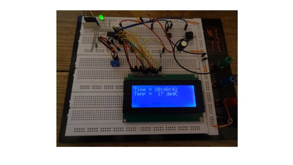
PIC Microcontroller project – 24 hour clock and thermometer displayed via 16f690 microcontroller and LCD programmed in CYou might be wondering why this project might be interesting to hi-fi enthusiasts. Well I have a few suggestions … the finished project will allow you to keep tabs on the temperature of your listening room via an LM35 temperature sensor, which is important not just for your own comfort, but electro-mechanical devices such as turntables, phono cartridges and loudspeakers or headphones perform best at temperatures that are comfortable to humans like you and me – 18 Celcius to 23 Celcius for example.

The other feature, the 24 hour clock is simply a clock as implemented at the moment, which is always useful in a gadget, but with additional software development could be used to time the hours of phono cartridge use, or if you have a valve amplifier the hours of valve usage. Either way it’s a great feature as it is and leaves further firmware development up to your imagination.

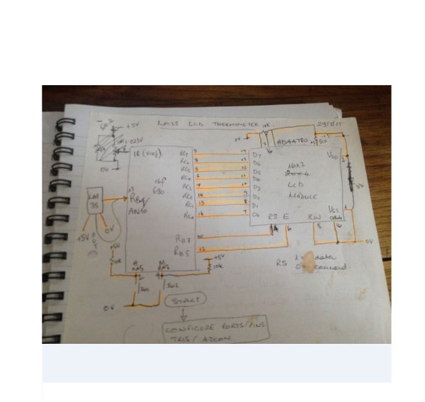
Here is a roughly drawn but accurate schematic circuit diagram and also the full C source code plus full build details – if you have any questions or queries please ask! Have fun…

Here’s a top view showing the sandwich construction of the thermo_timer – the front is a layer of 4mm clear acrylic, then brass pillars stand this off from the strip board circuit board. Another set of brass pillars then stand off the second layer of 4mm clear acrylic.

Here is the rear of the prototype which shows how simple the circuit really is – just a Microchip PIC 16f690, an LM35 temperature sensor which generates 10mV/ degree Centigrade, a contrast potentiometer for the LCD, and two push buttons to set hours and minutes of the clock.

And here is the C source code for the clock thermometer project, which has been complied with the free Microchip XC8 C complier and downloaded to the 16f690 with Microchip MPLABX IDE. Feel free to copy and use/ enhance this code to learn more about the C language and the PIC range of Microcontrollers, as I did and am still doing :-) I’d be really pleased if you would link to this page if you find it helpful.

/*
// File:   lcd_thermo_clock_16f690.c
* Author: Phil Glazzard
* version 1.03 – firmware modified 1 June 2015
* Created on 26 April 2015, 14:05 – MODIFIED TRM1 PRE-LOAD TO SLOW CLOCK 11/06/2015
*/
//0XDB CHANGED TO 0XA4 IN TMR1L

// PIC16F690 Configuration Bit Settings

// ‘C’ source line config statements

#include <xc.h>

// #pragma config statements should precede project file includes.
// Use project enums instead of #define for ON and OFF.

// CONFIG
#pragma config FOSC = INTRCIO   // Oscillator Selection bits (INTOSCIO oscillator: I/O function on RA4/OSC2/CLKOUT pin, I/O function on RA5/OSC1/CLKIN)
#pragma config WDTE = OFF       // Watchdog Timer Enable bit (WDT disabled and can be enabled by SWDTEN bit of the WDTCON register)
#pragma config PWRTE = OFF      // Power-up Timer Enable bit (PWRT disabled)
#pragma config MCLRE = OFF       // MCLR Pin Function Select bit (MCLR pin function is MCLR)
#pragma config CP = OFF         // Code Protection bit (Program memory code protection is disabled)
#pragma config CPD = OFF        // Data Code Protection bit (Data memory code protection is disabled)
#pragma config BOREN = OFF      // Brown-out Reset Selection bits (BOR disabled)
#pragma config IESO = OFF       // Internal External Switchover bit (Internal External Switchover mode is disabled)
#pragma config FCMEN = OFF      // Fail-Safe Clock Monitor Enabled bit (Fail-Safe Clock Monitor is disabled)
#define _XTAL_FREQ 4000000      // 4MHz clock defined for __delay_ms() function
#define RS PORTBbits.RB7        // RS = RB7
#define E PORTBbits.RB5         // E = RB5

int thous, huns, tens, units;   // define global variables
int temp, temp1;
char tick,seconds_lsb,seconds_msb, seconds, minutes,minute_msb, minute_lsb, minutes_msb, hundreds_lsb, hundreds_msb, hours = 0;
void config_timer1(void)
{
TMR1IF = 0;                 //clear timer1 interrupt flag
TMR1L = 0;                  // clear low byte of 16 bit timer1
TMR1H = 0;                  // clear high byte of 16 bit timer1
T1CONbits.T1CKPS0 = 1;      // select 1:8 pre-scaler
T1CONbits.T1CKPS1 = 1;
PIE1bits.TMR1IE = 1;        //enable timer1 interrupt
INTCONbits.PEIE = 1;        //enable peripheral interrupt enable
INTCONbits.GIE = 1;         // enable global interrupt enable
}
void timer1_on(void)
{
TMR1H = 0x0B;               // pre-load 16 bit timer1 with 0x0BA4
TMR1L = 0xA4;               // 0.5 sec/ 2Hz frequency before overflow
T1CONbits.TMR1ON = 1;       // start timer1
}
int interrupt isr (int)
{

if (TMR1IF == 1)                   // check to see if the interrupt was caused by TMR1 overflowing
{
TMR1ON = 0;                           // turn TMR1 off
seconds = seconds + 1;                // increment seconds variable
TMR1H = 0x0B;               // pre-load 16 bit timer1 with 0x0BA4
TMR1L = 0xA4;               // 0.5 sec/ 2Hz frequency before overflow
T1CONbits.TMR1ON = 1;       // start timer
TMR1IF = 0;                 // clear TMR1 interrupt flag
RA4 = seconds;              // flip RA4 each second to flash LED at 1 Hz

temp1 = ADRESL;              //store low byte of ADC conversion in temp1
temp1 =  temp1 + (ADRESH <<8);//shift high byte of ADC conversion 8 bits left
//and add to temp1 to give 10 bit ADC result.
temp = (int)(temp1 /0.2046);//cast expression as an integer to avoid floating
//point arithmetic.
// 102.3 = 5V (Vref)so 10mV = 1deg C = 102.3/500 = 0.2046
ADIF = 0;                    // clear the ADC interrupt flag ready for next conversion
}
}

void clock()
{
E = 1;                                  // creates a 1ms pulse to clock commands and data
__delay_ms(1);                          // into the LCD module
E = 0;
}

void lcd_initialisation()
{
__delay_ms(100);                // 100ms delay after ‘power on’
RS = 0;
PORTC = 0x30;                   //Function set RS RW D7 D6 D5 D4 D3 D2 D1 D0
__delay_ms(5);                 //               0 0  0  0  1  1  0  0  0  0 = 0x30
clock();
RS = 0;
PORTC = 0x30;                      //Function set RS RW D7 D6 D5 D4 D3 D2 D1 D0
__delay_us(100);                 //               0 0 0  0  1  1  0  0  0  0 = 0x30
clock();
RS = 0;

PIC Microcontroller project – 24 hour clock and thermometer displayed via 16f690 microcontroller and LCD programmed in C SchematicPORTC = 0x30;                     //Function set RS RW D7 D6 D5 D4 D3 D2 D1 D0
__delay_us(100);                 //               0 0  0  0  1  1  0  0  0  0 = 0x30
clock();
RS = 0;
PORTC = 0x38;                   //Function set RS RW D7 D6 D5 D4 D3 D2 D1 D0
clock();                        //              0 0  0  0  1  1  1  0  0  0 = 0x38
__delay_us(200);
RS = 0;
PORTC = 0x08;                   //Display off
clock();
__delay_ms(1);
RS = 0;
PORTC = 0x01;                   // clear display
clock();
__delay_ms(10);
RS = 0;
PORTC = 0x06;                   // entry mode set
clock();
__delay_ms(1);
RS = 0;
PORTC = 0x0C;                   // LCD display ON, cursor off, cursor blinking off
clock();
__delay_ms(1);}
void clear_lcd()
{RS=0;
PORTC = 0x0F;
clock();
__delay_ms(1);}

void config_ports(void)

{


For more detail: PIC Microcontroller project – 24 hour clock and thermometer displayed via 16f690 microcontroller and LCD programmed in C

The post PIC Microcontroller project – 24 hour clock and thermometer displayed via 16f690 microcontroller and LCD programmed in C appeared first on PIC Microcontroller.
Microcontroller based Data Logger

$
0
0

Description:

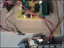
This project is a fine combination of analog and digital electronics. This project is designed so as to fulfill the requirements of the industry applications, home applications. The project consists of parameters monitoring, parameter storage. PC interface is one of the main features of the project in which various data like value of parameters, date and time are sent to the PC using a hyper terminal.

We have used Microcontroller as a main component of the project. Now a Microcontroller has become a main component of many of the electronic circuits. Also Liquid Crystal Display (LCD) and EEPROM is used on major basis for the display and storage purpose. This project which will consist of two basis modules. First is “Data Monitoring” & other is “Data Storage”

Microcontroller based Data LoggerA display unit will show the value of parameters. This will help for the person to know the values, for this purpose we are going to use various sensors, which will be connected to ADC.

The other module is named as parameter storage. It can be used to store the parameter values in the memory. We are going to use EEPROM memory IC. These values can later seen using a keypad provided on the front panel. This system is useful as many times its difficult to measure the parameter values manually and also this module is more accurate than the domestic system.

Description in detail:

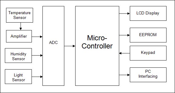
Explanation of Block Diagram:

1) SENSOR ONE: This is first sensor which uses to sense parameter one. This can be temperature sensor, say LM35. The sensor will be placed on the front panel. One can use LCD display to read the temperature.

2) SENSOR TWO: This is second sensor which uses to sense parameter two. This can be Humidity sensor, say LDR. The sensor will be placed on the front panel.

3) AMPLIFIER: We are going to use LM324 which is having 4 inbuilt amplifiers. Since we have two sensors, we have used this Amplifier.

4) ADC: We are going to use ADC 0808 which is 8 bit and 8 channel ADC. Since we have two inputs for ADC, we have used this ADC.

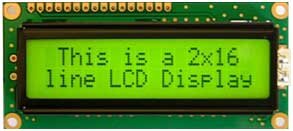
Microcontroller based Data Logger Schematic5) LCD: Liquid Crystal Display which is commonly known as LCD is an Alphanumeric Display it means that it can display Alphabets, Numbers as well as special symbols thus LCD is a user friendly Display device which can be used for displaying various messages unlike seven segment display which can display only numbers and some of the alphabets. The only disadvantage of LCD over seven segment is that seven segment is robust display and be visualized from a longer distance as compared to LCD. Here WE have used 16 x 2 Alphanumeric Display which means on this display WE can display two lines with maximum of 16 characters in one line.


For more detail: Microcontroller based Data Logger

Current Project / Post can also be found using:

  • PC data-logger bluetooth microcontroller

The post Microcontroller based Data Logger appeared first on PIC Microcontroller.

How to Interface LCD with PIC16F877A Slicker

$
0
0

PIC16F/18F Slicker Board

The PIC16F/18F Slicker board is specifically designed to help students to master the required skills in the area of embedded systems. The kit is designed in such way that all the possible features of the microcontroller will be easily used by the students. The kit supports in system programming (ISP) which is done through USB port.

Microchip’s PIC (PIC16F877A), PIC16F/18F Slicker Kit is proposed to smooth the progress of developing and debugging of various designs encompassing of High speed 8-bit Microcontrollers.

How to Interface LCD with PIC16F877A SlickerLCD (Liquid Crystal Display)

Liquid Crystal Display also called as LCD is very helpful in providing user interface as well as for debugging purpose. A liquid crystal display (LCD) is a flat panel display that uses the light modulating properties of liquid crystals (LCs). LCD Modules can present textual information to user.

Interfacing LCD

Fig. 1 shows how to interface the LCD to microcontroller. The 2×16 character LCD interface card with supports both modes 4-bit and 8-bit interface, and also facility to adjust contrast through trim pot. In 8-bit interface 11 lines needed to create 8-bit interface; 8 data bits (D0 – D7), three control lines, address bit (RS), read/write bit (R/W) and control signal (E).

nterfacing LCD with PIC16F877A

We now want to display a text in PIC16F/18F Slicker Board by using LCD module. In PIC16F/18F Slicker Board contains the LCD connections in a single header.

How to Interface LCD with PIC16F877A Slicker SchematicThe PIC16F/18F Slicker board has eleven numbers of LCD connections, connected with I/O Port lines (PORTE.0 – PORTE.3 && PORTD.0 – PORTD.7) to make LCD display.

Source Code

The Interfacing LCD with PIC16F877A program is very simple and straight forward, which display a text in 2 X 16 LCD modules. Some delay is occurring when a single command / data is executed.


For more detail: How to Interface LCD with PIC16F877A Slicker

Current Project / Post can also be found using:

  • 16f84a lcd project tutorials
  • how to interfacing pic 18f4520 with lcd display assembly code
  • i2c Glcd ccs c
  • pasword bass door lock pic micro

The post How to Interface LCD with PIC16F877A Slicker appeared first on PIC Microcontroller.
RFID Based Attendance System – Circuit, Working, Source Code

$
0
0

Attendance in colleges is generally paper based which may sometimes cause errors. Taking attendance manually consumes more time. So the proposed attendance system uses RFID technology to take attendance. In this system, each student is issued an RFID tag. Controlling unit is in the institute. Whenever the card is placed near the reader, it will take the attendance. This article explains the same. But, before going to read this post, once get an idea about how to interface LCD with AVR Microcontroller as it is also included in this circuit.RFID Based Attendance System Circuit Working Source Code

RFID Based Attendance System Circuit Principle:

RFID based attendance system consists of RFID Reader, RFID Tag, LCD display and microcontroller unit. RFID can be interfaced to microcontroller through USART. Data is transferred from RFID cards to reader and from there to microcontroller.

Radio frequency technology is used in many applications. RFID tags are of two types – 1) Passive Tags and 2) Active Tags. Passive tags contain 13 digit number tag inbuilt in it, where as active tag is read/write tag i.e. one can read from the tag and write to the tag. This project uses passive tag. In real time, one can issue active tags to the students, with their roll numbers as their tags. RFID reader contains a copper winding in it. This winding acts as an antenna.

When the tag is placed near the reader, due to the induced mutual inductance energy, data is transferred to reader. Reader then transfers data to the microntroller. Microcontroller checks for the data continuously, if any data is received, microcontroller compares the data in data base. If the tag is authenticated, microcontroller takes the attendance. Also you can check out the rfid based attendance system output video.

RFID Based Attendance System Circuit Diagram:

Circuit Components:

  • ATMEGA8 Microcontroller.
  • RFID Reader
  • RFID Tags.
  • LCD display

Circuit Design of RFID Based Attendance System:

RFID based attendance system has very simple circuit design. The RFID Reader has transmit and receive pins. These pins are connected to the transmit and receive pins of the micro controller i.e. PD0 and PD1 pins of microcontroller.VCC is connected to 5v and GND is connected to ground. If pins are not available to the module, connect it using DB9 connector. PD0 pin is receiver and PD1 pin is transmitter.RFID Based Attendance System Circuit Working Source Code schematic

Related Post: Biometric Attendance System using AVR Microcontroller.

RFID module communicates with the controller using USART, where USART is a communication protocol. USART is acronym for Universal Synchronous and Asynchronous Receive and Transmit. Serial data can be transmitted from RFID module to microcontroller using UART.

ATMEGA8 microcontroller has USART registers internally. One should declare these registers in order to transmit or receive data serially.

LCD display is connected to Port B of the microcontroller. Interfacing of LCD in 4 bit mode is in to microcontroller which is shown in the circuit diagram. D4 – D7 data pins are connected to the PB0 – PB3 pins of microcontroller. RS pin is connected to PB4, RW pin is connected to PB5 and enable pin is connected to PB6 of microcontroller. To display data on LCD, initially set the LCD in 4bit mode. Then make Rw pin low, RS pin high, enable pin high. Send the data on data pins and make enable pin low.

DOWNLOAD PROJECT CODE

RFID based Attendance System Circuit Simulation Video:

For more detail: RFID Based Attendance System – Circuit, Working, Source Code

Current Project / Post can also be found using:

  • RFID BASED ATTEDANCE SYSTEM USING IR SENSOR SOURCE CODE

The post RFID Based Attendance System – Circuit, Working, Source Code appeared first on PIC Microcontroller.
Serial Data Received from PC and Displayed on 16×2 Using USART of Pic16f877 Microcontroller

$
0
0

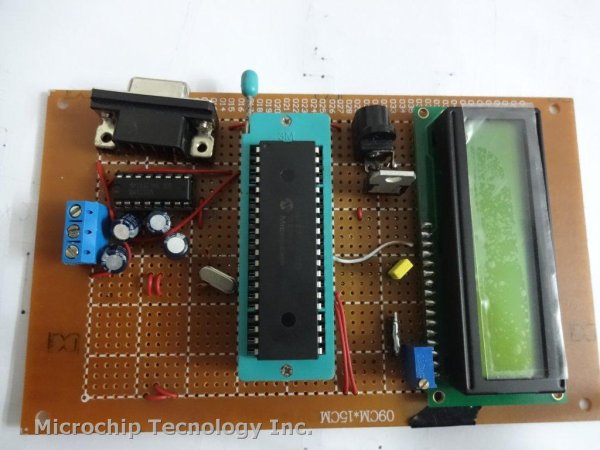
Here is a simple tutorial on how to receive serial data from PC(Personal Computer) Hyperterminal and display it on 16×2 lcd using PIC16f877 microcontroller. Its not much difficult you just need to know how to use USART(Universal Syncronous-Asyncronous receiver transmitter) of PIC 16f877. Serial data is transmitted and recived by PC using DB-9 OR DB-25 port of PC.Serial Data Received from PC and Displayed on 16x2 Using USART of Pic16f877 Microcontroller

Project Requirements

  • PIC16f877 Microcontroller
  • 16×2 lcd
  • MAX232
  • PC with DB-9 or DB-25 Port
  • Potentiometer (For Setting LCD Contrast)
  • Crystal 20MHz
  • Connecting Wires & Power Supply


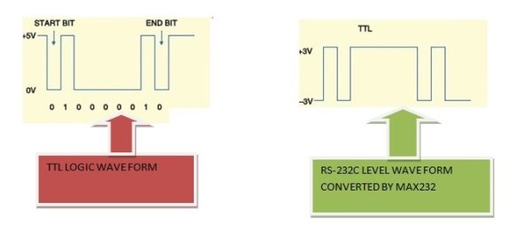
Microcontrollers works on TTL(Transistor Transistor Logic) wave form & Standard PC(Personal Computers) works on RS-232 level wave form. Serial Data Transmi
tted by PC is in RS-232c level wave form. We have to convert this RS-232c  wave form data in TTL form, to pass it to PIC16f877. The best way is to use MAX-232 ic. MAX-232 converts RS-232c level wave form data in TTL & TTL data in RS-232c level. Below is a simple Diagram of both the wave forms.

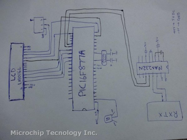
Port-B of PIC 16f877 is connected to data pins of 16×2 lcd. RS(Register-Select) Pin of lcd is connected to Port-D Pin#6. En(Enable) Pin of lcd is connected to Port-D Pin#7. RW(Read-Write) Pin is grounded Because we only want to write to lcd. You can also connect RW pin to Port-D Pin#5 Because Rw is also programmed in software burned in PIC 16f877.

USART of PIC 16f877 is present at Pin 25 & 26 of PIC 16f877 Microcontroller. USART Include Port-C Pin#6 & 7. RC6 can be used as TX(Transmission) and RC7 can be used as RX(Reception). Since we are receiving data from PC and then displaying it on 16×2 lcd so we are only concerned with RX(Reception) pin of USART. This RX pin is connected to Pin#12(R1OUT) of MAX-232. Pin#13(R1IN) of MAX-232 is connected to PIN#3 of DB-9 Port.
Some Tutorials Regarding the project are.


Both the tutorials above are very important for you, if you are new and didn’t use the stuff before in any project. I recommend you to go through them it will help you a lot in understanding the circuit diagram and working of both the things. Circuit diagram of the project is given below.
Serial Data Received from PC and Displayed on 16x2 Using USART of Pic16f877 Microcontroller schematic

Code is written in c language using MPLAB-ide and High Tech C compiler is used to compile the code. First High Tech C-compiler header file htc.h is imported in the project. Then Crystal frequency is defined which is 20MHz. RD7,RD6 & RD5 pins of Port-D are initialized as EN, RS & RW, Control pins for 16×2 lcd. lcdcmd() function is sending commands to lcd and control these commands. display() function is sending data to lcd, controls this data by controlling EN,RW & RS pins of lcd. lcdint() function is initializing our lcd and Microcontroller ports.

In the main function first TRISC7=1 is initializing RX pin as input. TXSTA(Transmit Status and Control Register) is initializing USART in Asyncronous Mode with High Speed Baud Rate. 0x04 is loaded in TXSTA.

RCSTA(Receive status and control register) Register is used for enabling USART of PIC 16f877. To enable USART make bit#7 (SPEN) high. I loaded 0x90 in RCSTA. Which enables our serial port and continuously receives data from PC.


Current Project / Post can also be found using:

  • 16×2 lcd with serial port micro c
  • how to program lcd 16×2 in pic 16f877a
  • project pic16f870
  • project using an lcd with pic16f877a

The post Serial Data Received from PC and Displayed on 16×2 Using USART of Pic16f877 Microcontroller appeared first on PIC Microcontroller.
WHAT IS A PIC MICROCONTROLLER? WHAT CAN IT DO?

$
0
0

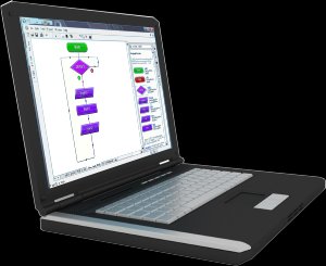
PIC microcontrollers ( Programmable Interface Controllers), are electronic circuits that can be programmed to carry out a vast range of tasks. They can be programmed to be timers or to control a production line and much more. They are found in most electronic devices such as alarm systems, computer control systems, phones, in fact almost any electronic device. Many types of PIC microcontrollers exist, although the best are probably found in the GENIE range of programmable microcontrollers. These are programmed and simulated by Circuit Wizard software.WHAT IS A PIC MICROCONTROLLER WHAT CAN IT DO
PIC Microcontrollers are relatively cheap and can be bought as pre-built circuits or as kits that can be assembled by the user

You will need a computer to run software, such as Circuit Wizard, allowing you to program a PIC microcontroller circuit. A fairly cheap, low specification computer should run the software with ease. The computer will need a serial port or a USB port. This is used to connect the computer to the microcontroller circuit.

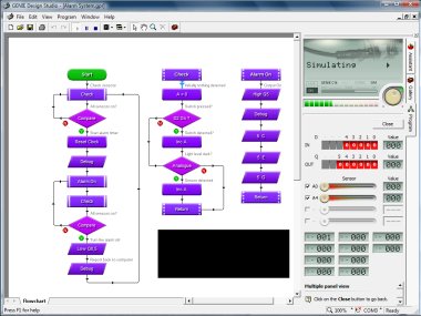
Software such as, Genie Design Studio can be downloaded for free. It can be used to program microcontroller circuits. It allows the programmer to simulate the program, before downloading it to a PIC microcontroller IC (Integrated Circuit).
Simulating the program on screen, allows the programmer to correct faults and to change the program.
The software is quite easy to learn, as it is flow chart based. Each ‘box’ of a flow chart has a purpose and replaces numerous lines of text programming code. This means that a program can be written quite quickly, with fewer mistakes.

class=”style7″ class=”style6″ width=”50%”>A USB lead connects the computer to the programmable circuit, allowing the transfer of the program to the PIC microcontroller IC

When the program has been simulated and works, it is downloaded to the PIC microcontroller circuit. The USB lead can be disconnected and the microcontroller circuit can be used independently. The diagram below, shows a GENIE Project Board being programmed by Circuit Wizard software (recommended software for programming microcontroller circuits).WHAT IS A PIC MICROCONTROLLER WHAT CAN IT DO schematic

Circuit Wizard software has major advantages over free downloads. It is a ‘simple to use’ electronics software package. Basic up to complex circuits, can be built on screen and simulated. This means that circuits can be tested before they are manufactured.

Circuit Wizard also allows a range of GENIE Microcontroller circuits/project boards, to be ‘dragged’ on to the screen, from a menu. Inputs and outputs can be added using further menus. Then, the GENIE microcontroller circuit/project board can be programmed, using Circuit Wizard’s flow charting menu. It can be fully tested/simulated on screen and faults corrected or alterations made. This software is strongly recommended, when designing and manufacturing microcontroller programmable circuits.


For more detail: WHAT IS A PIC MICROCONTROLLER? WHAT CAN IT DO? 

Current Project / Post can also be found using:

  • Lcd 16×2 pic mplab
  • lcd for microcontroller project
  • new microcontroller witheasy display

The post WHAT IS A PIC MICROCONTROLLER? WHAT CAN IT DO? appeared first on PIC Microcontroller.
How to display custom characters on LCD using PIC16F877

$
0
0

This post explains the idea of creating custom characters on any LCD ( e-g on 16×2 LCD ) which has HD44780U controller in it. Almost all 16×2 or 20×2 LCDs have HD44780U controller in them[1]. This controller provides the functionality of CGRAM ( Character Generator RAM ). We can write character patterns on this RAM and then they can be easily displayed on the LCD. The code for custom character generation using PIC16F877 microcontroller and Proteus simulation can be downloaded from the ‘Downloads‘ section at the bottom of this page.

display custom characters on LCD using PIC16F877

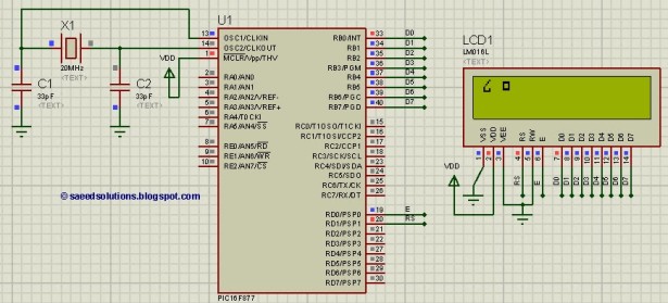
If you don’t know how to interface LCD with PIC16F877 in 8bit mode, then you should read this post first. The required circuit for displaying custom characters on LCD is shown below.

PORTB is being used as data bus for the LCD. Also, RD1 pin is used as RS (Register Select for LCD) and RD0 pin is used as E (Enable pin for LCD).

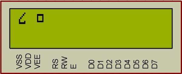
A crystal of 20 MHz is used here. You can use any crystal value from 0 to 20MHz in this circuit. Close-up picture of the LCD is shown below.

How to generate custom character ?

I am going to explain custom character generation using an example. In the figure 2, first character displayed on the LCD is named ‘Curvy Object’ in the code. To generate this character, First make a box of 8 by 5 dots. Then fill the dots required to make the custom character you want to display. Following figure explains this concept.

After filling the dots, find out the value of each line. For example, ( in the figure 3 for ‘Curvy Object’ creation ) first line has a value of 0x01, because only first dot ( at 20 position ) needs to be displayed. Then second line has a value of 0x02, because only one dot at 21 position needs to be displayed. Similarly, third line has a value of 0x04, fourth line has a value of 0x08 and fifth line has a value of 0x10. Sixth line has the two dots to be displayed, hence 0x10 + 0x01 = 0x11 is it’s value. Seventh line has all the dots to be displayed, which corresponds to a value of 0x10 + 0x08 + 0x04 + 0x02 + 0x01 = 0x1F. Eight line has no dots to be displayed, so it has a value of zero. After finding out these values make an array of these values as shown in the figure 3. This array named ‘CurvyObject‘, which has 8 bytes of data will be transmitted to the CGRAM of LCD.

display custom characters on LCD using PIC16F877  schematic

We can program 8 custom characters when we are using 5×8 font in the LCD settings. And we can program 4 custom characters when we are using 5×10 font in the LCD settings. I have used 5×8 font in the code, hence at most 8 custom characters can be programmed. Using the approach to make the custom character described above, 2 custom characters were defined in the code. These custom character arrays are shown below[2].

Code

The code for the InitLCD() function is shown below[3]. This function is used to initialize the LCD properly with the custom characters.

Downloads

Custom character display on LCD code for PIC16F877 was compiled in MPLAB v8.85 with HI-TECH C v9.83 compiler and simulation was made in Proteus v7.10. To download code and Proteus simulation click here.


For more detail: How to display custom characters on LCD using PIC16F877

Current Project / Post can also be found using:

  • how to interface LCD with PCI16F

The post How to display custom characters on LCD using PIC16F877 appeared first on PIC Microcontroller.
Viewing all 253 articles
Browse latest View live


<script src="https://jsc.adskeeper.com/r/s/rssing.com.1596347.js" async> </script>