Quantcast
Channel: LCD Projects - PIC Microcontroller
Viewing all 253 articles
Browse latest View live

Interface a HD44780 Character LCD with a PIC Microcontroller

$
0
0

Introduction
An HD44780 Character LCD is a liquid crystal display (LCD) display device designed for interfacing with embedded systems. These screens come in a variety of configurations including 8×1, which is one row of eight characters, 16×2, and 20×4. The most commonly manufactured configuration is 40×4 characters, which requires two individually addressable HD44780 controllers with expansion chips as the HD44780 can only address up to 80 characters.
Interface a HD44780 Character LCD with a PIC MicrocontrollerThese LCD screens are limited to text only and are often used in copiers, fax machines, laser printers, industrial test equipment, networking equipment such as routers and storage devices. Character LCDs can come with or without backlights, which may be LED, fluorescent, or electroluminescent. Character LCDs use a standard 14-pin interface and those with backlights have 16 pins.

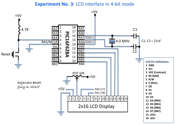
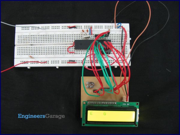
I am going to show you how to interface such a LCD to a PIC microcontroller (PIC16F628A). The programming for PIC will be done in mikroC (a C compiler for PIC from mikroelektronika).

he software is here:

 Note: Never forget to disable the comparator functions on PORTA.0, 1, 2, 3 pins if you are going to use those pins as digital I/O.

Interface a HD44780 Character LCD with a PIC Microcontroller/*

 * Project name:
     Test LCD in 4-bit mode
  * Description:
     This code demonstrates how to display test message on a LCD which
     is connected to PIC16F628A through PORTB. D4-D7 pins of LCD are
     connected to RB4-RB7, whereas RS and EN pins connected to RA0 and RA1

The post Interface a HD44780 Character LCD with a PIC Microcontroller appeared first on PIC Microcontroller.


Build your own “2-Wire LCD Interface” using the PIC16C84 microcontroller

$
0
0

2-Wire LCD Interface for the PICMicro

Alphanumeric LCD displays have become very popular for microcontroller applications because they can add a lot to a project in a variety of different ways. A text message giving the user instructions as well as feedback can make the application seem much more “professional” and easy to use. I like to use LCD’s to help debug applications, with breakpoints set to display variable and I/O conditions and they are a lot cheaper than using a microcontroller emulator. To top it off, surplus LCD’s can be found for a dollar or less.

The most popular LCD interface is the Hitachi 44780 based LCD controller chip which provides a fairly easy to work with interface and low power consumption. The major drawback of the interface is the perceived complexity of working with the interface. This perception has been promoted by the lack of good (i.e. well translated) and accurate datasheets and web site information.

Build your own 2-Wire LCD Interface using the PIC16C84 microcontrollerThis has been largely mitigated by the availability of a new data sheet from Hitachi; (available at here and user sites (such as my own at LCD Page with accurate information and example code that can be downloaded.

Often the biggest stumbling block to using alphanumeric LCD displays is the number of pins required to control them. For the Hitachi 44780, twelve pins are required from the microcontroller to interface to the display for it to work in eight bit mode. For many smaller microcontrollers, twelve pins are not available or will be better served in the application. To be fair, this can be reduced to six by using the 44780’s “Four Bit” mode, but this can still be more than acceptable for most applications.

A popular solution that only requires one pin from the microcontroller to the LCD is the use of “Serial LCD Interfaces” (such as Wirz Electronics “SLI-OEM” – http://www.wirz.com/) which convert “NRZ” serial data (either CMOS/TTL or RS-232 voltage levels) to the data and signals necessary for the Hitachi 44780 controllers.

Many of these products (such as the SLI-OEM) are excellent and can provide useful product interface and debugging information. The only drawback to them is the need for properly timed NRZ serial data which may be difficult or even impossible to guarantee in some applications.

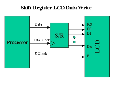
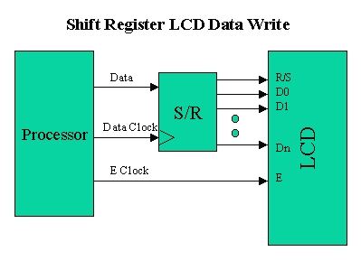
In this case, different approaches have to be made. The most popular one is to use synchronous serial data (requiring a “clock” and “data”) pin to load a serial-in/parallel-out shift register with the data bits and “R/S” pin information. The “E” Strobe Pin is driven directly by the microcontroller to latch in the data from the LCD. This is shown in the diagram below:

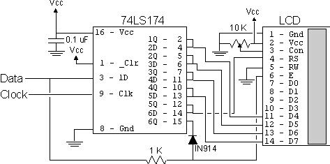
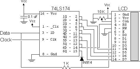
The project presented in this article is an enhancement of this circuit. By combining the shift register’s “Data Line” with the most significant bit of the shift register, the “E” Strobe can be implemented without resorting to a separate line for the function. The 1 K resistor and diode act as an “AND” gate. A schematic of the circuit is shown below.

The operation of the resistor/diode “AND” gate may not be immediately obvious. When the shift register bit is low, the diode pulls the connection to the “E” pin low. When the shift register bit is high, the diode will not cause any current flow from the connection at the “E” pin to the shift register. The resistor from “Data” to the “E” pin is a current limiting resistor. When the shift register bit is low and the data bit is high, then the current through the resistor will be limited to 5 mA (for a 5 Volt logic application). At the “Data” side of the resistor, the voltage will still be high, even though the diode is pulling the “E” pin low.

When both the “Data” line and the shift register bit are high, the “E” pin will be high. The “AND” circuit could be a TTL two input AND gate (such as a 7408), if you have an extra one available for your application. When I originally created this circuit, I used the same two transistor and two resistor circuit that I used for the 89C2051 emulator in “Programming and Customizing the 8051 Microcontroller”. I saw this “AND” equivalent circuit in an old copy of “Electronics Now” and found that it worked well in this application.

To load the shift register, it first has to be cleared to ensure that the “E” will not be strobed to the LCD inadvertently. This is done by first shifting in six “0”s to make sure that while the correct data is being loaded into the shift register, no “high” voltage level is passed to the “E” pin of the LCD.

 Build your own 2-Wire LCD Interface using the PIC16C84 microcontroller SchematicOnce this is done, the data can be shifted in. The diagram below shows how the shift register is initially cleared and then loaded with the data to be strobed (using “E”) into the LCD:

The application code, “2wirelcd.asm” is an assembler source file written for the PIC16C84. The file is written to be used with the “MPASM” assembler built into Microchip’s “MPLAB”. I wrote the code with the idea that it should be easily portable to any low-end or mid-range PICMicro without modification.

For the two I/O pins (“Data” and “Clock”), I “defined” them to allow you to use virtually any pins in your PICMicro application. I say “virtually any” because PORTA pin 4 (also known as “RA4″) is of “open drain” configuration and cannot source a positive voltage. The code itself is a very straightforward example of writing a 4-bit LCD application which displays the string “Hello” on the LCD display. The important difference between this code and a straight 4-bit LCD output is the “NybbleOut” subroutine, which is called twice by each of the “SendCHAR” and “SendINS” subroutines (which send characters and instructions, respectively, to the LCD).


For more detail: Build your own 2-Wire LCD Interface using the PIC16C84 microcontroller


The post Build your own “2-Wire LCD Interface” using the PIC16C84 microcontroller appeared first on PIC Microcontroller.
PIC 16C84 VT-52 Emulator for Linux

$
0
0

Features

  • Fits in one half height 5.25″ drive bay.
  • Back light 16 x 2 lines LCD (Hitachi Compatible) display.
  • 4 Selection buttons, arranged so that it looks like an ATM machine.
  • RS232 19,200 baud connection to PC with Hardware handshaking (CTS).
  • Uses a subset of the standard VT-52 control codes to control the LCD.
  • 3.6864MHz crystal make baud rate calculations easy.
  • Should be easy to port to BSD, SCO OpenServer,
    SCO Unixware, SUN Solaris or anything that has a serial port.
  • Doesn’t use any fancy or hard to get parts, all available
    off the shelf from Maplin Electronics (UK). However, some of the spacers
    needed to be cut to fit.

PIC 16C84 VT-52 Emulator for LinuxWhy?!

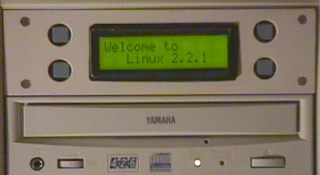
If you have read the other pages on this site you’ll know that I’ve got a Linux machine on a shelf in my room that provides all sort of useful services. It’s got no monitor or keyboard, and sometimes this can be annoying. What I wanted was a small display that I could check on that state of the machine and perform some useful actions – like a controlled shutdown, mount or un-mount devices – that type of stuff.

I like electronics and a few years ago began experimenting with Microchip’s PIC16C84. I bought five of these devices for a knock down price and so I’m now putting them to use. The ’84 isn’t the best tool for the job as it lacks a UART, this is no big deal really – it just makes the software on the PIC more interesting.

Problems and Limitations

Reading RS232 is quite a CPU intensive operation for the ’84 as you must poll and sample the RS232 waveform in software in order to determine the whole byte. As soon as the PIC detects that a transmission is on its way it uses CTS to inform the host device not to send any more data until it is ready for more. This gives the PIC enough time to control the LCD or perform other in house tasks. Unfortunately there is a problem with this. 16550A PC serial port chipsets under Linux send 8 bytes then see if the remote device can handle any more. If you use this PIC on one of these serial ports only every 8th byte is correct, the rest are corrupt because they were sent while the PIC wasn’t ready. The solution to this problem is fortunately very easy to fix. You need to tell Linux to control the serial port like an old style 8250 that had no fancy buffers. So.

setserial /dev/ttyS1 uart 16450

will fix this problem on Linux, I’m not sure about other Unix’s.

Because of the polled serial reading it is possible for the start bit to arrive while the PIC is in the middle of the interrupt routine to poll the buttons. A corrupted byte (or two) is likely to be read. This doesn’t happen very often, if fact I’ve not seen it happen yet – but it’s statistically likely to happen. The solution to the is to use a real UART or a PIC with a UART. I’ve recently made some adjustment to the code to tighten the timing up, it’s now very unlikely to get corrupted characters.

What needs changing or fixing when you build the next version?

  1. Button repeat in the PIC code.
  2. Use round buttons to match the round holes!
  3. The display does not scroll, I’d need an extra control line to the LCD to do this which with the current PIC I don’t have. However, there are ways to get round this by multiplexing the LCD data lines with the buttons.
  4. Full duplex using a lower baud rate, and that should eliminate the need for hardware handshaking. 2400 baud might be OK…

PIC 16C84 VT-52 Emulator for Linux SchematicWhat VT-52 codes does it understand?

ESC E Clear display and reset cursor to top left.
ESC T not a VT code. This is something I’ve put in that displays a test pattern, used to check the RS232 output serial code in the PIC.
ESC H Resets the cursor to the top left, but does not clear the display.
ESC Y Position the cursor, format of the command is ESC Y (32+Y) (32+X) so ESC Y !! sets the cursor to 1,1.
ESC e Cursor visible.
ESC f Cursor off.

That’s it, there isn’t very much point implementing the rest, some code are impossible to do with the LCD anyway – like inverse video and colours.


For more detail: PIC 16C84 VT-52 Emulator for Linux

The post PIC 16C84 VT-52 Emulator for Linux appeared first on PIC Microcontroller.

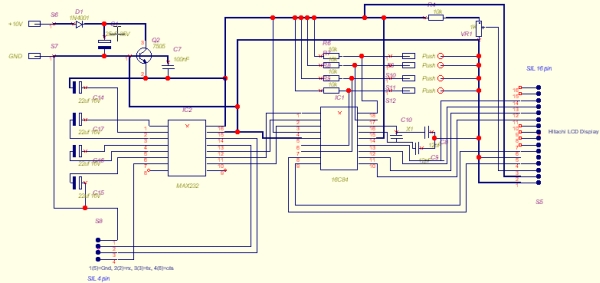
Low cost LCD module interface with optional LED backlight using PIC18F452

$
0
0

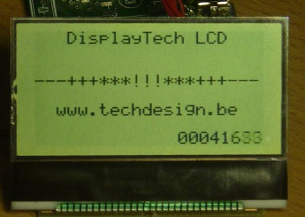
Here are the technical specifications:

  • LCD resolution: 128 x 64 pixels
  • LCD manufacturer: DisplayTech.
  • LCD model 1: 64128COG-FA-BC (no backlight)
  • LCD model 2: 64128G-FC-BW-3 (white LED backlight)
  • On-glass lcd controller KS0713, with 30 pins connector.
  • Very low power operation (less than 1mA @3V)
  • Fast serial interface (only 8 wires needed)
  • Molex miniature connector.
  • LCD: dimensions: 56 x 41 mm
  • PCB interface: Dimensions: 44 x 18 mm

LCD module


These two LCD modules can be bought in our online shop. You’ll need the interface described below and a PIC microcontroller to get these LCD modules running.

PIC example Source code (CCS C) , pcb layout and schematics (Eagle) available.  Last update: March 24, 2007.

PIC software example: routines

ccs routine example explanation
LCD initialization dt_lcd_init(); init parameters needed after power on
Clear screen dt_lcd_clear_screen(); resets all pixels, needed after power on
Cursor position set dt_lcd_gotoxy(0,5); goto cursur location x= 0..127 PIXEL COLUMNS // y= 0..7 CHAR. ROWS
Write text to LCD printf(dt_lcd_printchar,” DisplayTech LCD”); show simple unformatted text


Downloads: right-click & save as

Interface: Eagle PCB layout: 042 – 004.brd  – March 24, 2007.

 Interface: Eagle Schematics: 042 – 004.sch  – March 24, 2007.


 PIC CCS example: source code: 042_v01.zip for 18f452 @ 20MhZ – March 24, 2007.

 PIC CCS example:Hex file: 042_v01.hex for 18f452 @ 20MhZ – March 24, 2007.


For more detail: Low cost LCD module interface with optional LED backlight using PIC18F452


The post Low cost LCD module interface with optional LED backlight using PIC18F452 appeared first on PIC Microcontroller.

Serial LCDs you can make your own using PIC12F683

$
0
0

HD44780 based LCD displays are very popular for embedded projects because they are cheap, easy to interface, can display characters, consume power lot less than seven-segment displays, and most of the present day compilers have in-built library routines for them. However, the only disadvantage is that they require at least 6 I/O pins of microcontroller. Well, you may ask, isn’t that less than what seven-segment displays require? Yes, that’s true but there are circumstances where you don’t have left enough pins for LCD display. For example, if you are going to design a temperature sensor based on a PIC12F683 microcontroller, which has just 6 I/O pins, you won’t have pins for interfacing a LCD. One solution for cases like that is to use serial LCD’s. Serial LCD’s available in the market cost more than double of HD44780 based standard one. The serial LCD’s still have the standard LCD module but it has an extra built-in driver module that receives data/command from a host microcontroller in serial format and convert it to appropriate parallel format suitable for HD44780 driver input.

3 Wire LCD

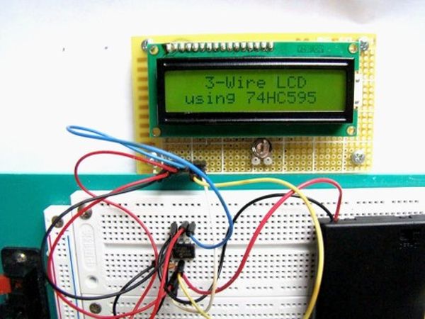
The goal of this project is to show how to make a 3-wire serial LCD driver for low pin-count microcontrollers like PIC12F series using a serial-in parallel-out shift register (74HC595 in this case). PIC12F683 has been chosen here to test the end product. Since 74HC595 is just a shift register with no intelligence of its own, the burden goes to the host microcontroller (PIC12F683) to appropriately transfer the LCD character/command data and control signals in serial format. This part of the intelligence is embedded in the firmware inside PIC12F683. So, a portion of program flash memory inside PIC12F683 is sacrificed for this purpose. The required three pins of PIC12F683 performs following functions.

  1. Serial data transfer to 74HC595
  2. Clock signal for the Shift/Storage register
  3. Enable signal to HD44780 LCD Module

74HC595 Shift Register

74HC595 is a high-speed 8-bit serial in, serial/parallel-out shift register. It also has a storage register and 3-state outputs. The two registers (shift and stoarge) have separate clocks, SH_CP and ST_CP respectively. Data in the shift register is shifted on the positive-going transitions of SH_CP, and the content of shift register will be transferred to the storage register on a positive-going transition of the ST_CP. If both the clocks are together, the shift register will be one clock ahead of the storage register. The output enable (OE) pin, when pulled Low, enables the 8-bit data of the storage register to show up at the parallel output (Q0-Q7).

SH_CP and ST_CP clocks are tied together for this purpose and are driven together by a microcontroller pin. So, the storage register output (Q0-Q7) is 1 clock behind the shift register, and an additional clock pulse is required after the last bit is fed to the serial input so that it would appear at the output.

HD44780-based character LCD

HD44780 based character LCD displays use 14 wire connections: 8 data lines (D0-D7), 3 control lines (RS, E, R/W), and three power lines (Vdd, Vss, Vee). Some LCDs come with backlight features that help reading display data in low illumination conditions. They have two additional connections  (LED+ and LED-).


For more detail: Serial LCDs you can make your own using PIC12F683

The post Serial LCDs you can make your own using PIC12F683 appeared first on PIC Microcontroller.

Interfacing LCD Modules with PIC Microcontrollers.

$
0
0

A large number of embedded project require some type of user interface. This includes displaying numerical, textual and graphical data to user. For very simple numerical display we can use 7 segment displays. If the requirement is little more than that, like displaying some alphanumeric text, we can use LCD Modules. They are cheap enough to be used in low cost projects. They come in various sizes for different requirement. A very popular one is 16×2 model. It can display 2 lines of 16 characters. Other models are 16×4,20×4, 8×1,8×2 etc.

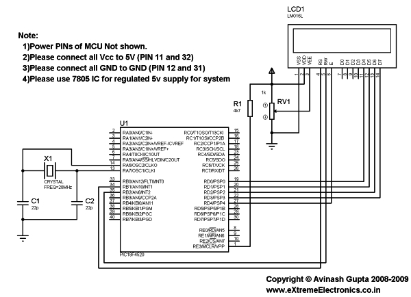
In this tutorial we will learn how we can use such modules with Microchip PIC Microcontrollers. Here I will present my LCD library which you can use to create LCD based application/projects quickly. For demo I will use PIC18F4520 Microcontroller but you can use any PIC18 MCU. But you have to calculate the CONFIG values for correct setting and CPU clock selection etc. That means the chip should be configured correctly. See datasheet for more info on CONFIG bytes.

Interfacing LCD Modules with PIC Microcontrollers. MPLAB Project Creation

First create a MPLAB project as described in this tutorial. Name the project LCD. Also add a main file called “lcd_test.c”. To use my LCD library you need to add it to your project. Just copy/paste the following files to your project folder.

Header Files

  • lcd.h
  • myutils.h

Source File

  • lcd.c

How to add files to MPLAB Project is described here.

Now you are ready to the library functions to interact with the LCD module.

Interfacing LCD Modules with PIC Microcontrollers SchematicSample Program (lcd_test.c)

/********************************************************************

16X2 ALPHANEUMERIC LCD INTERFACING LIBRARY TEST PROGRAM

---------------------------------------------------------

A testing program for our LCD library.

Easy to use library for interfacing 16x2 lcd in 4 bit mode.
MCU: PIC18FXXXX Series from Microchip.
Compiler: HI-TECH C Compiler for PIC18 MCUs (http://www.htsoft.com/)

Copyrights 2008-2009 Avinash Gupta
eXtreme Electronics, India

For More Info visit
http://www.eXtremeElectronics.co.in

Mail: me@avinashgupta.com

********************************************************************/
#include <htc.h>

#include "lcd.h"

//Chip Settings
__CONFIG(1,0x0200);
__CONFIG(2,0X1E1F);
__CONFIG(3,0X8100);
__CONFIG(4,0X00C1);
__CONFIG(5,0XC00F);
//Simple Delay Routine
void Wait(unsigned int delay)
{   for(;delay;delay--)      __delay_us(100);}void main()
{   //Let the Module start up   Wait(100);   //Initialize the LCD Module
   LCDInit(LS_BLINK);   //Clear the Module
   LCDClear();   //Write a string at current cursor pos
   LCDWriteString("Good Is Great !!");

   Wait(20000);   //Now Clear the display
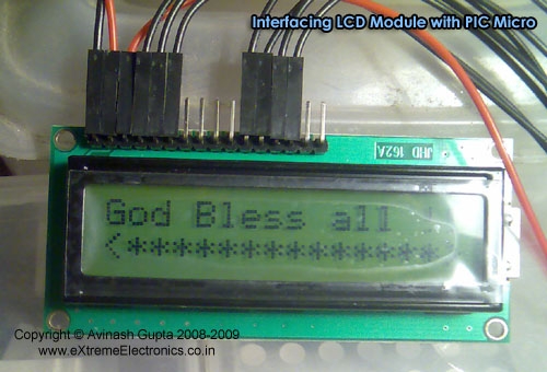
   LCDClear();   LCDWriteString("God Bless all !!");
   //Goto POS (X=0,Y=1 i.e. Line 2)
   //And Write a string
   LCDWriteStringXY(0,1,"<**************>");
   Wait(20000);   //Write Some Numbers
   for(char i=0;i<100;i++)
   {         LCDClear();  LCDWriteInt(i,3); Wait(3000);   }
   LCDClear();   LCDWriteString("    The  End    ");
   //Loop Forever   while(1);}


For more detail: Interfacing LCD Modules with PIC Microcontrollers. 

The post Interfacing LCD Modules with PIC Microcontrollers. appeared first on PIC Microcontroller.

LCD Serial Terminal using PIC16F84

$
0
0

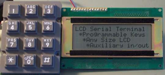
LCD Serial Terminal

Introduction:
In the 1980s a serial terminal was a big thing with a picture tube and keyboard. You used it to communicate with a computer by RS-232 cable or with a modem. In this century, we still sometimes have need for a serial terminal, and we’ll typically use a personal computer running a terminal program (Hyperterminal, bundled withWindows, is a terminal program). This project is a self-contained serial terminal using a PIC16F84 microcontroller chip, an inexpensive LCD character display, a keypad, and very little else. It is full-duplex, meaning keypresses cause RS-232 output, and RS-232 input makes characters appear on the LCD. If you connect the RS-232 output to the input you can see the keys as you press them, without connecting to anything else (that’s called “looping back”).

LCD Serial Terminal

Project Description:
The picture above doesn’t show the electronics, just a keypad and LCD display. The electronics is on a small board behind the LCD. This LCD is a 4 line by 20 character intelligent LCD display. Displays from 1×8 to 4×20 or 2×40 and pretty much anything in between are compatible. I paid less than US$10 for this display from All Electronics. The keyboard you use should be a matrixed keyboard or keypad with up to 5 rows and 4 columns (20 keys maximum).

This small PC board is the terminal itself. Someday I will document a PC board design, but currently I am only making available the schematic diagram, source code for the PIC16F84, and compiled hex code for a typical configuration so you can quickly test it out. The source code is in C and very easily configured for different baud rates, LCD and keypad configurations. The program should be compiled with Hi-Tech PICC. A free version supporting the PIC16F84 called “PICLITE” is available and works fine.

The mapping of the keys is fully configurable, and each key can also be configured for one of four different modes. Each key is allowed to have a primary code and a secondary code. Depending on what mode is chosen, the secondary code might be sent when the key is released, or when the key is held more than one second, etc. Key repeat is also programmable, and each key can have a different mode.

Many cursor movement features are implemented, all the standard ones (backspace, carriage return etc.) and if you tell the program your LCD format, text will flow from line to line.

For more detail: LCD Serial Terminal using PIC16F84

Current Project / Post can also be found using:

  • serial terminal microcontroller graphics lcd display

The post LCD Serial Terminal using PIC16F84 appeared first on PIC Microcontroller.

Serial LCD Library using PIC16C84

$
0
0

Here is a library to interface your PIC code to an LCD that is controlled via a serial line. One such LCD is available from Scott Edwards Electronics. There are many others, and the code shown here can easily be adpated to other LCD displays by changing some defines.

Serial LCD Library

The following files are referenced below, but for simplicity I’ve listed them here for download:

  • LCDlib.tar.gz is my entire LCD library and associated test source code in gzip’d tar format.
  • LCDlib.zip is my entire LCD library and associated test source code in zip format for Windows PCs.
  • lcd.c the library C source.
  • lcdtest1.c tests printing an integer in decimal and hex format (lcdtest1.hex).
  • lcdtest2.c tests positioning the cursor for printingt (lcdtest2.hex).
  • lcdtest3.c tests scrolling the LCD display left and rightt (lcdtest3.hex).
  • lcdtest.jpg a schematic showing how to wire the PIC to the serial LCD module.

The following routines are defined:

  • void lcd_putc(char c) send the byte c to the LCD
  • void lcd_clear(void) clears the LCD screen
  • void lcd_home(void) homes the LCD cursor
  • void lcd_puts() print a string **UNIMPLEMENTED**
  • void lcd_printhex(char c) prints byte c as a 2 digit hex character
  • void lcd_printdec(char c) prints byte c as a decimal digit string
  • void lcd_printbin(char c) prints byte c as a binary string
  • void lcd_scroll_left(char n) scrolls LCD screen left n positions
  • void lcd_scroll_right(char n) scrolls LCD screen right n positions
  • void lcd_goto(char row, char col) goto a location

The LCDPORT and LCDPIN constants define which port and logical pin the serial LCD is connected to. By default they are set to PORTA and pin 1 which is the RA1 output on phsyical pin 17 of a PICC84.

If you connect the serial LCD to a different port and pin then you must change the definitions in the lcd.c file.

void lcd_putc(char c) – send a byte to the LCD
This routine is the heart of the LCD library: it will send a byte specified in the argument c to the LCD connected to the port defined by LCDPORT and pin LCDPIN. All the other routines use this code. lcd_putc() assumes that the LCD is running at 9600 baud, 8-N-1 serial settings. If your LCD is running at a different baud rate, or you have a faster PIC, you will have to adjust the timing loop starting at lcdtxloop. The lcd_putc() routine places a 10ms pacing delay between each character.
void lcd_clear(void) – clear the LCD screen
Building upon the lcd_putc() routine is easy, as this routine shows. We simply send the byte sequence that clears the display.
void lcd_home(void) – home the LCD cursor
Sends the byte sequence that homes the LCD cursor to the top left hand corner.
void lcd_printhex(char c) – print byte as hex
Print a byte value on the display as 2 hex characters. For example, the value 255 would be printed as FF. The code prints the hi nibble first (the upper 4 bits of the byte), followed by the lower nibble.
void lcd_printdec(char c) – print byte as decimal
Print a byte value as a decimal string. For example, the value 123 is printed as the characters “123”. This function performs repeated subtractions: starting at 100, we subtract until the value left is less than 100. We then repeat the loop for 10’s. Whatever is left is the units value. Effectively, this routine performs division by repeated subtraction. The output of lcd_printdec() is always 3 digits long: 001 as against just 1.
void lcd_printbin(char c) – print byte as binary
This routine prints a binary representation of a byte. For example, 129 would be printed as 10000001. 8 bits are always printed, which means that the value may have leading zeros: 5 would be printed as 00000101.
void lcd_scroll_left(char n) – scroll screen left
Scroll the LCD display left n positions. The effect of this command depends a lot on the type of LCD display you have.
void lcd_scroll_right(char n) – scroll screen right
Scroll the LCD display right n positions. The effect of this command depends a lot on the type of LCD display you have.


For more detail: Serial LCD Library using PIC16C84

The post Serial LCD Library using PIC16C84 appeared first on PIC Microcontroller.


Easy Debugging Terminal using PIC16F84

$
0
0

Introduction

This LCD terminal provide two modes of operation by selecting jumper J1. When J1 is open the terminal operate as a normal ascii display terminal, when J1 is closed the terminal displays the input serial data in hexadecimal format. This mode is useful for viewing raw data from the serial port output.

Hardware

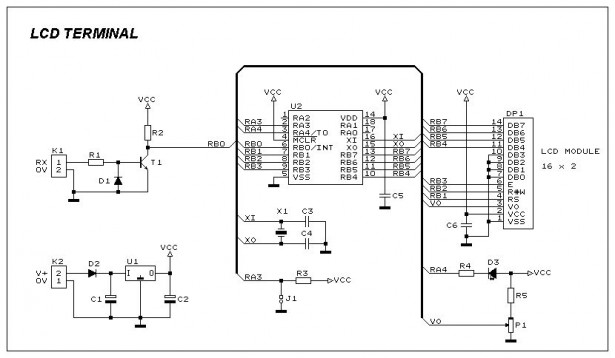
Figure 1 shows the circuit diagram of the Easy Debugging Terminal. IC U2 a PIC16F84 micro controller is used to control the operation of the terminal. Input signal is applied to connector K1. The circuit can be powered either by 9V dc adapter or by using a 9V battery. Jumper J1 select the operating mode of the terminal, J1 open for ascii terminal mode, closed for hexdecimal display mode. LED D3 can be controlled by software command provided in ascii mode. This LED output can also be used (with buffer circuit) to control the backlight of the LED backlit display. Variable P1 is used to adjust the contrast of the display. The circuit uses a 16×2 line LCD module, while a 16×1 module can also be used.

Constructing the Circuit

Debugging Terminal

The prototype board may be built using universal PCB having the same size as of LCD module so that LCD module can be mounted on top of universal PCB using SIP connectors.
For the parts list of the circuit view the file Lcdbom.txt


For more detail: Easy Debugging Terminal using PIC16F84

Current Project / Post can also be found using:

  • LCD project
  • pic prgrammes for lcd

The post Easy Debugging Terminal using PIC16F84 appeared first on PIC Microcontroller.

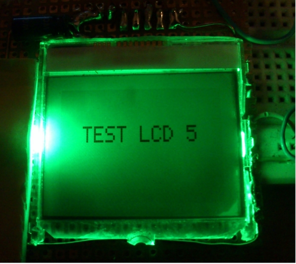
Nokia 3315 / 3310 LCD interfacing with Microcontroller

$
0
0

Displaying content on a normal alphanumeric display is very limited ,we have to be limited with the font size and we can’t draw any graphics also. but convention Graphics lcd are really very expensive so here is the solution, you can use Nokia 3315 / 3310 monochrome  LCD to display your large font text and graphics . the reason behind using this LCD is ,it is really very cheap and can be powered with 3 volts supply. so it is really good for battery powered application.

Project Description 

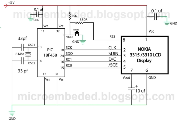
however you can use almost any microcontroller (with capability to work on 3v ) do display content on this LCD, may be that micro controller is PIC , AVR or MSP 430 , but in this demonstration we will be using Microchip PIC 18F458 Microcontroller.
Nokia 3315 3310 LCD interfacing with MicrocontrollerThe software program for this project will be written in C with MPLAB IDE , This LCD has a resolution of 84×48 pixel.

About LCD:-

Nokia 3315 / 3310 Graphical LCD uses PCD8544 Controller chip From Philips. It is a chip-on glass(COG) with  8 pin connector on the back side of the LCD . You can refer to its datasheet for more information about this controller. (CLICK HERE TO DOWNLOAD PCD8544 Controller DATA SHEET).we will discuss only few main points here for out project purpose.

The typical example of RAM is shown in the figure blow, The vertical axes area addressed form 0 to 5 with eight bits for each address when combining with x axes, it can be represented as bank.

The horizontal axes are addressed form 0 to 83 and each bit will refer the corresponding pixel in X direction.

Addressing Mode  
There are two type of addressing mode in this LCD
Vertical addressing Mode

A byte is sent to The LCD as follows:-
1:- Set SCE To GND
2.Set D/C to required state (Data or command)
3.Place a bit in SDIN line
4. Make high-to-low transition in CLK input.
5.Repeat step 3 and 4 for the remaining seven bits.

Nokia 3315 3310 LCD interfacing with Microcontroller Schematic

The initialization sequence of  LCD

1. Pull SCE line to Ground to Enable The LCD.
2 Set D/C pin low to send commands to the LCD.
3. Write 0x21 Byte to LCD on the serial Bus. Here the LCD operates in Function set Command For extended instruction set.
4. Write 0xC8 Byte to LCD on the serial Bus. This set the operating voltage (Vop) of the LCD.
  5. Write 0x06 Byte to LCD on the serial Bus. This set the temperature coeffcient.
  6.  Write 0x13 Byte To LCD on the serial Bus.  This set the bias system of the LCD. 
7.  Write 0x20 Byte To LCD on the serial Bus.  This allow the LCD to operate in function set command with basic instruction.


For more detail: Nokia 3315 3310 LCD interfacing with Microcontroller

Current Project / Post can also be found using:

  • serial interfacing lcd pic microcontroller
  • lcd on project
  • microcontroller phone interface
  • microcontroller projects with lcd

The post Nokia 3315 / 3310 LCD interfacing with Microcontroller appeared first on PIC Microcontroller.

LCD Module Control over IR Link using PIC16F690

$
0
0

Recently I got my hands on a couple of HSDL-1100 based IR transceivers and a KS070B LCD display module. This was a nice opportunity to experiment with three things: (1) controlling an LCD module, (2) serial communication between two PIC microcontrollers, and (3) making this work over an IR link.

LCD Module

Serial protocol supports addressing of up to 32 devices over shared media (IR or direct connection) and have basic error detection (2 inverse parity bits). Packets consist of 16 bits, as given below:

  • P0 – inverse parity of all even numbered bits [2-14]
  • P1 – inverse parity of all odd numbered bits [3-15]
  • Device ID – ID of the target device; LCD responds to ID 00001
  • C/D – Code or Data; if “1”, following byte contains command (for example, LCD “CLEAR SCREEN” command); if “0”, following byte contains data (in case of the LCD this would be code of a character to be displayed).

Data is encoded as a sequence of short pulses. The beginning of a data packet is shown below:


For more detail: LCD Module Control over IR Link using PIC16F690

The post LCD Module Control over IR Link using PIC16F690 appeared first on PIC Microcontroller.

Message Pump using PIC16F687 microcontroller

$
0
0

Brief:

The Message Pump A.K.A. the USB to LCD Backpack is a device that allows you to connect a LCD display directly to your computer. It uses a PIC micro-controller, to drive the LCD and a FTDI USB to serial chip to connect to your computer.

The great thing about the FTDI chip is that it’s drivers are available for Macintosh, Windows, and Linux! The FTDI chip works by creating a VCP (virtual com port) and you may already have these drivers on your computer if you use an Ardunio Diecimila. If not, no worries they are free and and easy install.

What does it do?

Once a VCP is opened to the Message Pump any ASCII serial data sent to it is displayed on the LCD display.

This means that if you have software on your computer that can access a serial port you can display messages on the Message Pump!

The possibilities are endless, imagine using AppleScript, Processing, Basic or whatever your preferred programming / scripting language is, you could display messages like;

Message Pump

  1. BulletHow many e-mails you have
  2. BulletThe current date and time
  3. BulletCPU temperature
  4. BulletRSS feeds
  5. BulletHits on your web page
  6. Bullet ….

How to use it-Basics:

The easiest way to use the Message Pump is to open Hyper-terminal or an other terminal software, select and open the COM port for the Message Pump, then just start typing. What you type is displayed directly onto the LCD display. If you are using other software you will have to check how to open a serial port in that software.

To get you started I’ve made a simple Processing example. It is called MessagePumpDemo.pde and uses the Serial Library included with Processing.

The way MessagePumpDemo works; first it lets you select a serial port, then it opens that port at the default baud rate of 9600 bps and prints pumps out a message. It also lets you send keystrokes to the display. It’s a building block for you to examine and make better.


How to use it-Advanced:

The Message Pump also accepts instructions to control settings and formatting. These are used to change things such as the size of display, for example 1×16 to a 4×20 character display, baud rate etc. You can also jump to a specific space on the display. The instructions also include the ability to pass though, Hitachi commands right into the display. For example; clear display, shift left etc.


An instruction is always three bytes long and it always starts with the hex value of 0x80. The next value is the instruction and the third is the value of the instruction.


For more detail: Message Pump using PIC16F687 microcontroller

Current Project / Post can also be found using:

  • ###########################
  • pic16f877 lcd display

The post Message Pump using PIC16F687 microcontroller appeared first on PIC Microcontroller.

PIC32 Multimedia Expansion Board Review Video

$
0
0

Review of the Multimedia Expansion Board for the PIC32 Start Kits from Microchip.
In this review I’m going to show the board and it’s periphirals, and then I will show a couple of demostration applications.

Current Project / Post can also be found using:

  • pic16f84a with lcd project circuit

The post PIC32 Multimedia Expansion Board Review Video appeared first on PIC Microcontroller.

How to interface 16×2 LCD in 4-bit mode with PIC18F4550

$
0
0

The 16×2 character LCD can work in two modes, namely, 8-bit and 4-bit. These modes basically correspond to the number of data pins used in interfacing LCD. 8-bit mode uses all the data lines and has been explained in LCD interfacing with PIC18F4550. In 4-bit mode, only four data pins of LCD are connected to the controller. This mode, thus, saves four pins of the controller unlike 8-bit mode. The configuration and display method of LCD in 4-bit mode has been explained here.

interface 16x2 LCD

The 8-bit mode of LCD interfacing with PIC has been explained earlier. In the 4-bit mode the (8-bit) data/command is sent in nibble (four bits) format to LCD. The higher nibble is sent first followed by the lower nibble. In 4-bit mode only four data pins (D4-D7) of LCD are connected to the controller. The control pins (RS, RW and EN) are connected the same way as in 8-bit mode. The connections of LCD with PIC18F4550 are shown in the adjoining circuit diagram. Please note that here only PortB is used to connect data lines as well as control lines unlike in 8-bit mode. Refer LCD interfacing with PIC in 8-bit mode.

LCD is configured for 4-bit mode by sending appropriate instruction known as Function Set. The Function Set is hexadecimal instruction for LCD MPU unit which selects the working modes of LCD. The Function Set is given below along with its description.
Instruction
RS
RW
D7
D6
D5
D4
D3
D2
D1
D0
Function Set
0
0
0
0
1
DL
N
F
-
-
Description: 
DL       –           Data Length
N         –           No. of Lines
F          –           Font
 Value
 DL
 N
F
1
8 bit
2 lines
5×10 dots
0
4 bit
1 line
5×7 dots
According to the table, the value of Function Set for 4–bit mode will be [ 0010 0000 ] 0x20. The value of Function Set for the LCD configuration : 2 line (N=1), 5×7 dots (F=0) and 4-bit (DL=0) mode will be [ 0010 1000 ] 0x28.
It is important to note that when the power supply is given to LCD, it remains in 8-bit mode. In this state if 0x20 is sent, lower nibble will not be received by LCD because only four data lines (D4-D7) are connected, so 0x02 is sent instead of 0x20.

The post How to interface 16×2 LCD in 4-bit mode with PIC18F4550 appeared first on PIC Microcontroller.

Displaying Images on Graphical Lcd(JHD12864E) using Pic16f877 Microcontroller

$
0
0

Here in this post i am going to teach you how to display images on Graphical lcd using Pic Microcontroller(16F877). I am using JHD12864E graphical LcD in my Project. JHD12864E is 128×64 dimension lcd. 128×64 means it has 128 coulombs and 64 rows. So total dots it has is 128×64=8192. You can display an image of maximum size(Dimension = 128×64) with in this range. Some notable things..

You can only display images of .bmp format. Images bitmaps are obtained only by .bmp format. Graphical lcds consists of dots, we have to display our images using these dots and .bmp image is also comprised of dots. we can easily find bits of images of .bmp format and can map them on Graphical lcd.

Displaying Images on Graphical Lcd(JHD12864E) using Pic16f877 MicrocontrollerYou can only display black and white images(Monochrome images bitmap is hard to generate. Non software is found for generating bitmap of monochrome images on internet).

  • If you want to display images of size greater than 128×64 than first change the size of the image. I used an online image dimension converter(My image size is 960×1280. I converted it to 128×64 using an online image dimension converter. You can found many tools to convert images just Google for it).  
  • If you are new to graphical lcd and didn’t know much about it just go through the tutorial below. You will become familiar with graphical lcd, its half and pages, its commands, its pin out and how to effectively use it. It will help you in understanding the code given below.
The first pic which i am going to display is mine(The Admin). Its original size is 960×1280, format is .jpg and its a monochrome pic. I converted it to black and white, format .bmp and size is reduced to 128×64 using an online software for image editing.
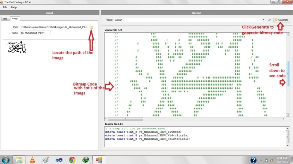
Now when you converted images its time to find bitmaps. Bitmaps are found using special softwares. I used an open source software The Dot Factory. Just give the path of the image and click generate it will generate bitmap with in a second. Download the software here… 
Dot factory not only generates bitmaps it also gives you the dimension of the newly generated bitmaps. Once bitmaps code is generated you can copy them from their and place them in your code.

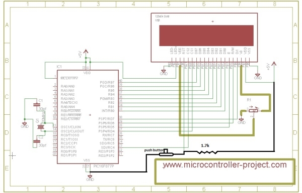
Pic16f877 microcontroller is used to display images on jhd12864E graphical lcd. Port-B is used to send data and commands to graphical lcd. It is connected to data pins D0-D7 of Graphical lcd. Lcd controlling pins en(Enable),rs(Register-select),rw(read-write) are connected to Port-D pins#7,6,5. Graphical lcd’s First-Half selection line is connected to Port-D Pin#4 and second-half selection line is connected to Port-C Pin#4.

oming to the code portion. Code is written in C++ language using MPLAB-IDE and HIGH-TECH C compiler is used to compile and generate hex code of the project.

Functions in the code with their functions are explained below….
Displaying Images on Graphical Lcd(JHD12864E) using Pic16f877 Microcontroller Schematicvoid delay(unsigned int d)
Delay Function is used to generate some arbitrary delay to be used in the code where necessary.
void lcdcmd(char value)
This function is sending commands to lcd. It not only send commands but also manipulate the lcd controlling pins(en,rw,rs) high and low to succesfully execute the commnad.
void lcddata(char data1)
This function is sending data to lcd. It not only send data but also manipulate the lcd controlling pins(en,rw,rs) high and low to succesfully display data on lcd.
void CS1()
This function is selecting first half of JHD12864E graphical lcd.
void CS2()
This function is selecting Second half of JHD12864E graphical lcd.
void createimage(const char *image)
Create image function is creating image on JHD12864E graphical lcd.

Current Project / Post can also be found using:

  • pic microcontroller scrolling images

The post Displaying Images on Graphical Lcd(JHD12864E) using Pic16f877 Microcontroller appeared first on PIC Microcontroller.


How to display custom characters on LCD using PIC16F84A

$
0
0

This post explains the idea of creating custom characters on any LCD ( e-g on 16×2 LCD ) which has HD44780U controller in it. Almost all 16×2 or 20×2 LCDs have HD44780U controller in them[1]. This controller provides the functionality of CGRAM ( Character Generator RAM ). We can write character patterns on this RAM and then they can be easily displayed on the LCD. The code for custom character generation using PIC16F84A microcontroller and Proteus simulation can be downloaded from the ‘Downloads‘ section at the bottom of this page.

Display custom characters on LCD using PIC16F84A

If you don’t know how to interface LCD with PIC16F84A in 8bit mode, then you should read this post first. The required circuit for displaying custom characters on LCD is shown below.

PORTB is being used as data bus for the LCD. Also, RA1 pin is used as RS (Register Select for LCD) and RA0 pin is used as E (Enable pin for LCD).

A crystal of 20 MHz is used here. You can use any crystal value from 0 to 20MHz in this circuit. Close-up picture of the LCD is shown below.

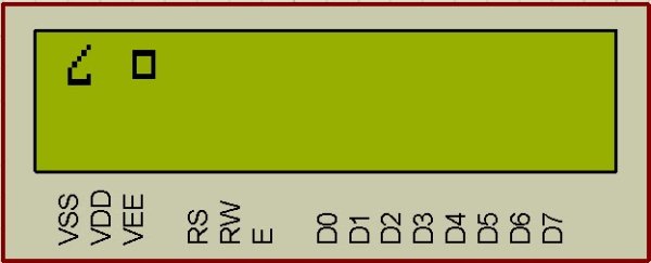
Figure 2 shows the custom characters displayed on the LCD by running the code.

How to generate custom character ?

I am going to explain custom character generation using an example. In the figure 2, first character displayed on the LCD is named ‘Curvy Object’ in the code. To generate this character, First make a box of 8 by 5 dots. Then fill the dots required to make the custom character you want to display. Following figure explains this concept.

After filling the dots, find out the value of each line. For example, ( in the figure 3 for ‘Curvy Object’ creation ) first line has a value of 0x01, because only first dot ( at 20 position ) needs to be displayed. Then second line has a value of 0x02, because only one dot at 21 position needs to be displayed. Similarly, third line has a value of 0x04, fourth line has a value of 0x08 and fifth line has a value of 0x10. Sixth line has the two dots to be displayed, hence 0x10 + 0x01 = 0x11 is it’s value. Seventh line has all the dots to be displayed, which corresponds to a value of 0x10 + 0x08 + 0x04 + 0x02 + 0x01 = 0x1F. Eight line has no dots to be displayed, so it has a value of zero. After finding out these values make an array of these values as shown in the figure 3. This array named ‘CurvyObject’, which has 8 bytes of data will be transmitted to the CGRAM of LCD.

Display custom characters on LCD using PIC16F84A schematic

Code

The code for the InitLCD() function is shown below[3]. This function is used to initialize the LCD properly with the custom characters.

Downloads

Custom character display on LCD code for PIC16F84A was compiled in MPLAB v8.85 with HI-TECH C v9.83 compiler and simulation was made in Proteus v7.10. To download code and Proteus simulation click here.


For more detail: How to display custom characters on LCD using PIC16F84A

The post How to display custom characters on LCD using PIC16F84A appeared first on PIC Microcontroller.

PIC16F84A LCD interfacing code (In 4bit mode) and Proteus simulation

$
0
0

This post provides the LCD[1] interfacing code in 4bit mode using PIC16F84A microcontroller. This code is written in C language using MPLAB with HI-TECH C compiler. You can download this code from the ‘Downloads‘ section at the bottom of this page.

PIC16F84A LCD interfacing 4bit mode

It is assumed that you know how to make an LED blink with PIC16F84A microcontroller. If you don’t then please read this page first, before proceeding with this article.

LCD interfacing circuit in 4bit mode with PIC16F84A is shown below.

In the above figure, RA0 pin is being used as Enable pin for LCD. RA1 pin is used as RS pin and RB4 to RB7 pins are being used as Data bus for the LCD. When code starts runing then Hello is displayed on the LCD.

Any 16×2 LCD can be used here which has HD44780U controller in it. For example, JHD162A LCD can be used with this code easily.


Code

The code for the main function is shown below.

In the main function, firstly LCD is initialized using InitLCD() function. After that, “Hello” is written on the LCD screen[2]. In this way using WriteDataToLCD() function, you can write any character on the LCD screen.

PIC16F84A LCD interfacing 4bit mode schematic

InitLCD() function initializes the LCD[3] by giving the initializing commands required to turn the LCD on. This function is shown below.

Downloads

LCD interfacing code in 4bit mode using PIC16F84A was compiled in MPLAB v8.85 with HI-TECH C v9.83 compiler and simulation was made in Proteus v7.10. To download code and Proteus simulation click here.


For more detail: PIC16F84A LCD interfacing code (In 4bit mode) and Proteus simulation

The post PIC16F84A LCD interfacing code (In 4bit mode) and Proteus simulation appeared first on PIC Microcontroller.

How to implement free running counter in PIC16F84A using seven segment display

$
0
0

This post provides the implementation of free running counter ( using c language ) for PIC16F84A micro-controller. This code is written in such a way that, the counter starts from a value of ‘0’ ( displayed on the seven segment ) and then increments this value after every second. So, the seven segment display starts from ‘0’ and then displays ‘1’, ‘2’, ‘3’, ‘4’, ‘5’, ‘6’, ‘7’, ‘8’, ‘9’, ‘A’, ‘b’, ‘C’, ‘d’, ‘E’, and in the end ‘F’. After displaying ‘F’, counter starts from ‘0’ again and this pattern repeats forever.

PIC16F84A using seven segment display

The code and Proteus simulation is given in the ‘Downloads‘ section at the bottom of this page. It is assumed that you know how to make an LED blink with PIC16F84A micro-controller. If you don’t, then please read this post first.

The following figure shows the circuit of free running counter in Proteus.

A crystal of 20 MHz is used here. You can use any crystal value from 0 to 20MHz with PIC16F84A. As we know that PIC16F84A microcontroller has an architecture which executes an instruction in 4 CPU cycles [1], hence this 20Mhz crystal makes this PIC16F84A run at 5.0 MIPS (Million of instructions per second).

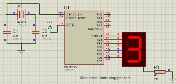
PORTB is used here to connect PIC16F84A with the seven segment display. RB0 pin is attached with the ‘a’ segment of the seven segment display. Similarly, RB1 pin is connected with ‘b’ segment, RB2 pin is connected with ‘c’ segment and so on.

Common cathode seven segment display is used in this example. You can easily modify this circuit and code for the common anode seven segment display as well.

PIC16F84A using seven segment display schematic

Code

The following function is used in the code to display values on the seven segment display.

Downloads

Free running counter code using PIC16F84A was compiled in MPLAB v8.85 with HI-TECH C v9.83 compiler and simulation was made in Proteus v7.10. To download code and Proteus simulation click here.


For more detail: How to implement free running counter in PIC16F84A using seven segment display

Current Project / Post can also be found using:

  • project LCD

The post How to implement free running counter in PIC16F84A using seven segment display appeared first on PIC Microcontroller.

Using an LCD’s for Graphics Animation using PIC16C84

$
0
0

This project uses Myke’s 2-Wire LCD Interface from last week
and will help teach you “Graphics Animation” using LCD’s.

Last week, I showed how the PICMicro could be connected up to a Hitachi 44780 LCD using only two wires. This week, I wanted to use this circuit and show how simple graphic animation can be displayed on an alpha-numeric LCD display very easily. The technique used is “Character Rotation”, in which motion is simulated in a manner that is very similar to cartoon animation.

LCD

In cartoon animation, a series of pictures are photographed in which each one is slightly different from the previous one in the sequence. When these pictures are displayed rapidly enough (usually greater than 15 times per second), the human eye perceives that only one picture is displayed and the characters on the picture are actually moving. By photographing these pictures onto movie film and running them at more than 15 frames per second, the average human can be convinced that a road runner can dupe a coyote into running into his own leg hold trap and then over a cliff where a cannon ball will crush him into an accordion.

A similar process and result can be accomplished with a Hitachi 44780 based LCD Display. The basic 44780 has an approximate ASCII character set built in. When an ASCII character is sent to the display, it is converted into a seven high by five wide series of “pixels” (dots) which appear, to the user as a character.

I say that the character set “approximates” the ASCII character set because some characters (most notably the backward slash – “\”) are not present and the ASCII Control characters (everything less than 0x020) show up as characters and do not perform their assigned actions. Part of the area reserved by ASCII for Control Characters, from 0x000 to 0x007, can be used by an application to display custom (“user defined”) characters. These eight characters can be set up and used by an application very easily.

The user defined characters have their pixel patterns stored in a separate memory area within the Hitachi 44780 known as the “CGRAM”. This is an acronym for “Character Generator Random Access Memory”. Inside the 44780, character pixel patterns are generated from memories. For the most part (248 characters), this is a “ROM” (“Read Only Memory”) character generator which has been predefined and cannot be changed or defined by the user. The remaining eight characters have a “RAM” character generator which can be written to and when the representative character is to be displayed, the user defined pixel patterns is used instead of a predefined one.

This aspect of user or application pixel definition is why I usually refer to these eight characters as the “user defined characters”. If no pixel pattern is written to the 44780 and a character from 0x000 to 0x007 is displayed, then a random pixel pattern will be displayed.

If you power down the LCD display and display the character again, chances are the pixel pattern will be different. This is because the RAM does not power up to a set value and means that if you want to use the user defined characters, you have to make sure they are properly defined before they are displayed. Each byte within the CGRAM is used to display a line of pixels on the LCD display. The actual character definition is shown in the diagram below.

As can be seen in the diagram, the first line (or row) of pixels is at the character starting address in CGRAM with each line, going down, at an incrementing offset. When the 44780 was designed, the engineers took into account how people think and made it easy to figure out which bits are displayed for each row. Bit 0 of the row’s byte is on the right hand side of the eight by five character block; so to define a row, each pixel is represented as a bit in the byte and if the pixel is to be dark a “1” is placed in the byte that defines the row.

This is probably a bit hard to understand, to make it easier, I want to go through an example character that I created for the application that is presented later in this article.

To define a character, I usually take a piece of graph paper, outline an eight by five square box and draw the character inside it as I’ve shown in the diagram below:


For more detail: Using an LCD’s for Graphics Animation using PIC16C84

Current Project / Post can also be found using:

  • pic16c84 lcd
  • lcd projects using pic
  • PS/2 keyboard to PIC microcontroller to LCD display asm code

The post Using an LCD’s for Graphics Animation using PIC16C84 appeared first on PIC Microcontroller.

2-wire LCD interface using PIC16CF84

$
0
0

Alphanumeric LCD displays have become very popular for microcontroller applications because they can add a lot to a project in a variety of different ways. A text message giving the user instructions as well as feedback can make the application seem much more “professional” and easy to use. I like to use LCD’s to help debug applications, with breakpoints set to display variable and I/O conditions and they are a lot cheaper than using a microcontroller emulator. To top it off, surplus LCD’s can be found for a dollar or less.

The most popular LCD interface is the Hitachi 44780 based LCD controller chip which provides a fairly easy to work with interface and low power consumption. The major drawback of the interface is the perceived complexity of working with the interface. This perception has been promoted by the lack of good (i.e. well translated) and accurate datasheets and web site information.

2-wire LCD interface using PIC16CF84Often the biggest stumbling block to using alphanumeric LCD displays is the number of pins required to control them. For the Hitachi 44780, twelve pins are required from the microcontroller to interface to the display for it to work in eight bit mode. For many smaller microcontrollers, twelve pins are not available or will be better served in the application. To be fair, this can be reduced to six by using the 44780’s “Four Bit” mode, but this can still be more than acceptable for most applications.

A popular solution that only requires one pin from the microcontroller to the LCD is the use of “Serial LCD Interfaces”  to the data and signals necessary for the Hitachi 44780 controllers.

Many of these products (such as the SLI-OEM) are excellent and can provide useful product interface and debugging information. The only drawback to them is the need for properly timed NRZ serial data which may be difficult or even impossible to guarantee in some applications.

In this case, different approaches have to be made. The most popular one is to use synchronous serial data (requiring a “clock” and “data”) pin to load a serial-in/parallel-out shift register with the data bits and “R/S” pin information. The “E” Strobe Pin is driven directly by the microcontroller to latch in the data from the LCD.

2-wire LCD interface using PIC16CF84 SchematicThe project presented in this article is an enhancement of this circuit. By combining the shift register’s “Data Line” with the most significant bit of the shift register, the “E” Strobe can be implemented without resorting to a separate line for the function. The 1 K resistor and diode act as an “AND” gate.

The operation of the resistor/diode “AND” gate may not be immediately obvious. When the shift register bit is low, the diode pulls the connection to the “E” pin low. When the shift register bit is high, the diode will not cause any current flow from the connection at the “E” pin to the shift register. The resistor from “Data” to the “E” pin is a current limiting resistor. When the shift register bit is low and the data bit is high, then the current through the resistor will be limited to 5 mA (for a 5 Volt logic application). At the “Data” side of the resistor, the voltage will still be high, even though the diode is pulling the “E” pin low.


For more detail: 2-wire LCD interface using PIC16CF84

Current Project / Post can also be found using:

  • lcd pic project

The post 2-wire LCD interface using PIC16CF84 appeared first on PIC Microcontroller.

Viewing all 253 articles
Browse latest View live


<script src="https://jsc.adskeeper.com/r/s/rssing.com.1596347.js" async> </script>