Quantcast
Channel: LCD Projects - PIC Microcontroller
Viewing all 253 articles
Browse latest View live

HD44780 16×2 Char LCD Interfacing with microcontroller

$
0
0

Project Description:-

In this project we are going to learn various things about this chip set and displaying text on this LCD. The HD44780 16×2 char LCD screen Use 8bit and 4 bit parallel interface with backlight.

This Primary Objective in this project are:-

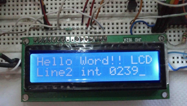
1.  Displaying  “Hello Word!! LCD ” message on the scree.
2.   Interfacing The LCD to the Microcontroller Using 8bit  Mode and 4 Bit Mode.
3.  Generating and Displaying Custom Char on the LCD Screen. clik here for custom char

Operation 

as i have mentioned  before this type of lcd are connected to microcontroller using parallel 8bit or 4bit lines.
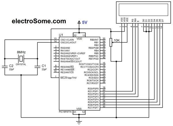
using 8 bit method is quite simple but take 8 lines (for data or command)+ 3 control signal total 11 line , i guess few small microcontrollers don’t even have that much of I/O lines ,so in 4 bit mode total 7 lines (sometimes 6 ) are required .  in this tutorial i will show you with both of the methods .

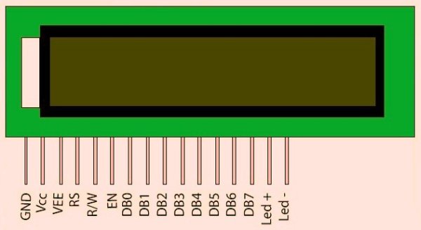
HD44780 16x2 Char LCD Interfacing with microcontroller Pin description

PIN NUMBER SYMBOL FUNCTION
1 Vss GND
2 Vdd  + 3V or + 5V
3 Vo Contrast Adjustment
4  RS H/L Register Select Signal
5 R/W H/L Read/Write Signal
6 E  H → L Enable Signal
7  DB0 H/L Data Bus Line
8  DB1 H/L Data Bus Line
9  DB2 H/L Data Bus Line
10  DB3 H/L Data Bus Line
11  DB4 H/L Data Bus Line
12  DB5 H/L Data Bus Line
13  DB6 H/L Data Bus Line
14  DB7 H/L Data Bus Line
15 A/Vee + 3.5V for LED/Negative Voltage Output
16 K K Power Supply for B/L (OV)

in 8 bit mode all the Data line DB0 to DB7 are being used for transferring the the data to lcd but in 4-bit mode only 4 line form DB4 to DB7 are being used to transfer the  8 bit wide data in two peaces one after another .

we can’t display any data on the lcd until all the required internal command register of the lcd are not being properly initialized.
to know every thing about this lcd controller .. you can go through it’s data sheet
click here to download HD44780 data sheet
so now we will learn how to initialize the lcd.

LCD Commands

Clear Display

clear  and place the cursor in the first position (address 0). The bit I / D to 1 by default.

RS R / W DB7 DB6 DB5 DB4 DB3 DB2 DB1 DB0
0 0 0 0 0 0 0 0 0 1

Return the cursor to Home

Place the cursor in the home position (address 0) and make the display starts to move from its original position. The contents of the RAM display data (DD RAM) remains unchanged. The address of the RAM for display data (DD RAM) is set to 0.

RS R / W DB7 DB6 DB5 DB4 DB3 DB2 DB1 DB0
0 0 0 0 0 0 0 0 1 X

Entry Mode in Set

Set cursor moving direction and specify that the display moves to the next position of the screen or not. These operations are performed during reading or writing of the DD RAM or CG RAM. To view usually set bit S = 0.

RS R / W DB7 DB6 DB5 DB4 DB3 DB2 DB1 DB0
0 0 0 0 0 0 0 1 I / D S

Display ON / OFF Control

Turn on or off by turning ON / OFF both the LCD (D) as the cursor (C) and whether or not this last flash (B).

RS R / W DB7 DB6 DB5 DB4 DB3 DB2 DB1 DB0
0 0 0 0 0 0 1 D C B

Cursor or Display Shift

Move the cursor to move the LCD without changing the memory contents of the display data DD RAM.

RS R / W DB7 DB6 DB5 DB4 DB3 DB2 DB1 DB0
0 0 0 0 0 1 S / C R / L X X

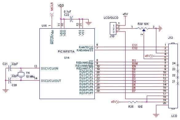
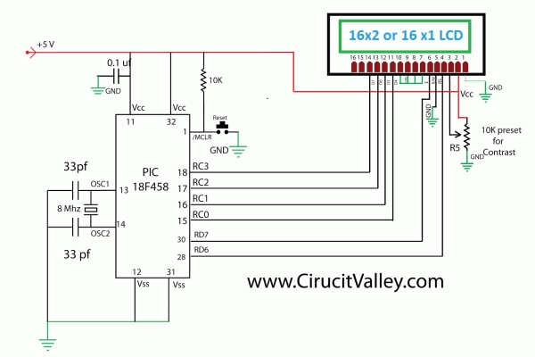
HD44780 16x2 Char LCD Interfacing with microcontroller SchematicFunction Set

Set the size of interface with the data bus (DL), number of lines in the LCD (N) and character type (F).

RS R / W DB7 DB6 DB5 DB4 DB3 DB2 DB1 DB0
0 0 0 0 1 DL N F X X

Set the CG RAM Address

The LCD module defined in addition to all the ASCII character set allows the user to define 4 or 8 characters. The composition of these characters is saved to a CG RAM memory called up to 64 bytes. Each user defined character consists of 16 or 8 bytes that are stored in successive positions of the CG RAM.

Using this instruction sets the CG RAM memory address from which the bytes will be stored that define a character. Running this command all the data that is subsequently read or write this memory made from CG RAM.


For more detail: HD44780 16×2 Char LCD Interfacing with microcontroller 

The post HD44780 16×2 Char LCD Interfacing with microcontroller appeared first on PIC Microcontroller.
1. Serial interfacing LCD with Pic Microcontroller

$
0
0
Parallel interfacing LCD with MCU at least need 6 I/O pins (4 bit mode) and maximun can up to 
11 I/O pins (8 bit mode). The I/O pin can be cut down to 3 pin by serial iterfacing using shift 
register. They were few shift register can be used such as 74HC164, 74HC595, CD4094 and any 
compatible 8 bit shift register. Before you attempt to do serial interfacing, it is good 
pratice to familiar with parallel interfacing. You can find many reference from internet. 
Following diagram show the serial interfacing Hitachi compatible 2 X 16 LCD modules with 
Pic16F84 or Pic16F628 MCU.

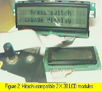
The Hitachi compatible 2 X 16 LCD modules drive by Pic16F84 MCU show on figure 1. The Hitachi compatible 2 X 20 LCD modules (optrex) drive by Pic16F84 MCU show on figure 2. When using this optrex 2 X 20 LCD modules, the Vref (pin 3 at LCD) need around -4.5v to -5.5V supply. The source code/hex file for Pic16f84 download here: F84SLCD.zip. The source code/hex file for Pic16f628 download here: 628SLCD.zip.

1. Serial interfacing LCD with Pic MicrocontrollerMore LCD reference can find here:

  1. www.myke.com
  2. www.eio.com
  3. www.repairfaq.org
  4. www.iaehv.nl
  5. www.shellyinc.com

2. Software SPI interfacing ADC with Pic16F84/Pic16F628

Communication with the MCP3028 ADC chip is done using a simple serial interface compatible
with the SPI protocol. The Pic16f84 or Pic16f628 didn't had hardware SPI peripheral. However, 
software implemeted SPI protocol can be done to communicate with 12 bit MCP3028 ADC device. 
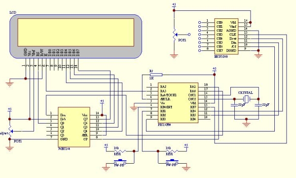
The example of this communication shown as following circuit diagram. The ADC result shown
on LCD with hex value (conversion from binary code). Press the push button (pin 6, RB0/INT)
to select the ADC channel (8 channel from CH0 to CH7). Then, connect the potention meter to
the channel and turn it. You will see the hex value change accordingly. The SPI communication 
protocol need 4 line for interfacing. Using software implemeted SPI protocol enable 
communication with more than one ADC device. 
The hex file for Pic16f84 download here: F84S_L.zip.
The hex file for Pic16f628 download here: 628S_L.zip.

3. Simple multi channel digital voltmeter

The circuit diagram same as above 12 bit ADC interfacing. The only different is the source code
which the binary code has been change to ASCII code with decimen number. This need some math 
fuction such as divide function and floating point. The math fuction for assembler code can 
find from Microchip Website www.microchip.com. You can also find some documen of math fuction 
from www.piclist.com or use C compiler such as Piclite for PIC16f8X/c8x series, cc5x c, 
pacific c and so on. The following hex file are use Microchip Math Library (assembler code) for 
this simple multi channel digital voltmeter device (using 16 bit for calculation). The maximum 
hex value for the ADC channel is FFF equal to decimel number 4095. This will display on the LCD 
as 5.11 volt.

Download hex file for Pic16F84 here: F84dec.zip.
Download hex file for Pic16F628 here: 628dec.zip.
*Tip on source code migration from Pic16f8X series to Pic16f62X series*
  1. If using PORTA pins as interfacing I/O, you need to define/set the I/O fuction for PIC16f628. Generally, the initial PORTA setting as following for I/O fuction: clrf PORTA movlw 0x07 ;turn comparators off and movwf CMCON ;enable pins for I/O functions Note: Ensure the above setting done at Bank 0. The above setting especially important if you want to migrate the source code from Pic16f8X series to Pic16f62X series.
  2. Always refer to data memory MAP (on Pic datasheet) to ensure that the general purpose register used not out of range when migrate one type of MCU to another type of MCU. As example, general purpose register for Pic16f84 was 0x00c to 0x04f (at bank 0). For Pic16f628 was 0x020 to 0x07f (at bank 0), 0x0a0 to 0x0ef (at bank 1) and 0x120 to 0x14f (at bank 2). It is better to define the address follow sequence.If out of range, you can re-define it easly.
  3. When Using bit 4 (RB4) of PORT B of Pic16F62X series as a output pin, ensure that the MCU not programmed at low voltage program mode (see Microchip datsheet) if not it will set as Schmitt Trigger input and independence of TRISB regeister I/O direction setting.

Serial interfacing LCD with Pic Microcontroller SchematicStepper motor controller

The stepper motor driver circuit shown as following
The opto-isolator are important which prevent destroy of MCU by the feeback voltage from 
power transistor. Two adjust-able voltage regulator used to adjust the running voltage and 
stopping/holding voltage of the stepper motor. The running voltage on by
the step pulse input which also signal to rotate the motor. The simple source
code using interrupt method to change the step sequence (one wave) download here:
F628_stepper for Pic16F628.
Simple mathematics algorithm able to drive more complicate step sequence (such as half step)
even for half_step 5phase stepper. 
Another stepper motor circuit for X-Y table project click here:X-Y table project

More stepper motor information refer to:

1)www.cs.uiowa.edu
2)www.ams2000.com

5). 24 segments LED display module

The numerical LED display module was widely used in display application. The most common numerical LED display module consists of either 8 segmented or 
16 segmented LED units. However, this type of display module only limited to display numerical character (0 to 9) and a few type of alphabet character. 
Most of alphabet word message displayed using alphanumerical LED modules with dot matrix arrangement.
The 24 segments LED display module designed in such a way that enable it to display  alphabet (A to Z) and numerical (0 to 9) character. 
This will able it to display most of word message using A to Z alphabet and numerical character when combine a few units of this module. 
The display controlling method also more simple than the dot matrix type of alphanumerical LED module.


For more detail: 1. Serial interfacing LCD with Pic Microcontroller

The post 1. Serial interfacing LCD with Pic Microcontroller appeared first on PIC Microcontroller.
Pic Projects With Schematics And Source Code

$
0
0
Circuit-Zone.com – Electronic Projects, Electronic – Project list | pic microcontroller, »circuit digital clock using pic16f628a microcontroller schematics » they act only ones – right then, when it´s really necessary » how to burn or program pic. Electronics projects circuits, Electroschematics.com: over 1050 top electronics projects and electronic circuits with photos, datasheets and easy to read schematics plus how it works and how to. Lcd projects – pic microcontroller, Build a simple 9600 baud 8n1 lcd terminal for debugging and testing the projects having rs232c output. introduction this lcd terminal provide two modes of operation.

Pic Projects With Schematics And Source Code Digital Thermometer Circuit Project

Pic-based applications westford microsystems, Westford microsystems westford, vermont, usa projects using microchip pic® mcus written in and featuring ccs c code last modified 01/15/2015 “but when the kindness.The microcontroller projects resources., “looking for the best microcontroller projects and resources?” here you can find microcontroller projects and tutorials designed by me a “professional.Microcontroller based circuits / projects tutorials, Home > electronic tutorials > quick reference links to some useful circuits > microcontroller based circuits / projects / tutorials: quick reference links for some.Circuit-zone. – electronic projects, electronic, Rotary encoders are very versatile input devices for microcontroller projects. they are like potentiometers expect of digital nature and unlike analogue.

Pic Projects With Schematics And Source Code Schematic

System Sequence Diagram Example

Microchip pic micros – source sample code, C sample code for pic micros and hi-tech c. sample projects for the microchip pic micro series of microcontrollers, including the pic12x, pic16x, pic18x, pic24x, and.Project list | pic microcontroller, »circuit digital clock using pic16f628a microcontroller schematics » they act only ones – right then, when it´s really necessary » how to burn or program pic.

Source : Pic Projects With Schematics And Source Code

The post Pic Projects With Schematics And Source Code appeared first on PIC Microcontroller.
PIC Microcontroller Based Electronic Lock

$
0
0

Security is a prime concern in our day-today life. Everyone wants to be as much secure as possible. An access control for doors forms a vital link in a security chain. The microcontroller based digital lock for Doors is an access control system that allows only authorized persons to access a restricted area.

PIC Microcontroller Based Electronic LockAn electronic lock or digital lock is a device which has an electronic control assembly attached to it. They are provided with an access control system. This system allows the user to unlock the device with a password. The password is entered by making use of a keypad.

The user can also set his password to ensure better protection. The major components include a Keypad, LCD and the controller PIC16F877A. This article describes the making of an electronic code lock using the 16F877A microcontroller.

The system is fully controlled by the 8 bit microcontroller 16F877A which has a 8Kbytes of ROM for the program memory. The password is stored in the EPROM so that we can change it at any time. The system has a Keypad by which the password can be entered through it. When the entered password equals with the password stored in the memory then the relay gets on and so that the door is opened.

PIC Microcontroller Based Electronic Lock schematic

The code is built in a modular style to allow a user to find ways to modify  project. In start the D Lock programs loads with a default code of “2345” format is *2345# which can be enter to unlock the door, the code cam be change by entering the master code in the format *23455#new 4 digit code.  In this program i only display the result on LCD and lock will be  placed at   PORTA bit 0 where i put led for simulation.

A 4×3 matrix keypad and a 16×2 LCD have been used here. Keypad and LCD are very commonly used input & output devices, respectively. The password is stored in the system EEPROM.


For more detail: PIC Microcontroller Based Electronic Lock

The post PIC Microcontroller Based Electronic Lock appeared first on PIC Microcontroller.
Up-Down counter on 16*2 LCD using 8051 microcontroller

$
0
0

DESCRIPTION

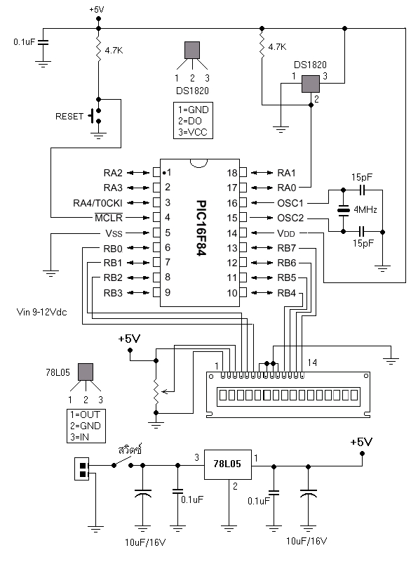
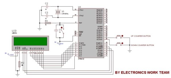
In this circuit 16*2 lcd IS used to show the value of count using 8051 microcontroller. The maximum value of count is 99 because. In this circuit we are using 8051-microcontroller, 16*2 lcd, 2 switches for up counting button & down counting button. Data pins of LCD are connected to P1 port of the 8051 microcontroller. UP counter button is connected with P2.6 and down counter button is connected with P2.7.Whenever the UP counter button is pressed the counter increments by one and when the down counter button is pressed it gets reduced by one.

Up-Down counter on 162 LCD using 8051-Microcontroller-Projects

PROJECT CODE

#include< reg51.h >

sfr lcddata=0x90; //LCD DATA PINS
sbit rs=P3^2;
sbit rw=P3^3;
sbit en=P3^4;
sbit g=P2^6;
sbit h=P2^7;

int m=0;
int a,b;
unsigned char n[10]={0x30,0x31,0x32,0x33,0x34,0x35,0x36,0x37,0x38,0x39};

void delay(unsigned char b)
{
unsigned char a;
for(b;b>0;b–)
{
for(a=500;a>0;a–);
}
}

void command(unsigned char dost)
{
lcddata=dost;
en=1;
rs=0;
rw=0;
delay(5);
en=0;
}

void lcddisplaydata(unsigned char n)
{
lcddata=n;
en=1;
rs=1;
rw=0;
delay(50);
en=0;
}

void main()
{
P2=0xFF;
command(0x38);
command(0x0C);
while(1)
{
if(g==0)
{
if(m==99)
{
command(0x80);
lcddisplaydata(n[9]);
command(0x81);
lcddisplaydata(n[9]);
}
else
{
m=m+1;
a=m/10;
{
command(0x80);
lcddisplaydata(n[a]);
}
b=m%10;
{
command(0x81);
lcddisplaydata(n[b]);
}
while(g==0);
}
}

Up-Down counter on 162 LCD using 8051-Microcontroller schematic

if(h==0)
{
if(m==0)
{
command(0x80);
lcddisplaydata(n[0]);
command(0x81);
lcddisplaydata(n[0]);
}
else
{
m=m-1;
a=m/10;
{
command(0x80);
lcddisplaydata(n[a]);
}
b=m%10;
{
command(0x81);
lcddisplaydata(n[b]);
}
while(h==0);
}
}
}
}


For more detail: Up-Down counter on 16*2 LCD using 8051 microcontroller

The post Up-Down counter on 16*2 LCD using 8051 microcontroller appeared first on PIC Microcontroller.
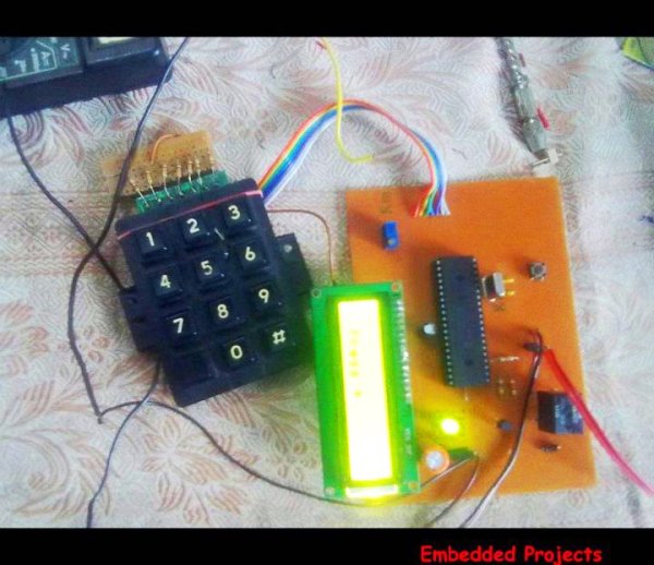
Interfacing LCD with PIC Microcontroller – CCS C

$
0
0

In this tutorial we will see How to interface a 16×2 character LCD Module with PIC 16F877A Microcontroller using CCS C Compiler. 16×2 character LCD is a very commonly used LCD module in electronic projects and products. 16×2 means it can display 2 rows of 16 characters. It is a very basic and low cost module. Its other variants such as 16×1, 20×4 are available in the market. In these displays each character is displayed using 5×8 or 5×10 dot matrix. These LCDs commonly uses HD44780 compliant controllers for their operation.

Interface between a microcontroller and LCD can be 4-bit or 8-bit. The difference between 4-bit and 8-bit is how data are send to the LCD. To write an 8-bit character to the LCD module in 8-bit mode, ASCII data is send through the data lines DB0- DB7 and data strobe is given through the E line.

Interfacing LCD with PIC Microcontroller – CCS CBut 4-bit mode uses only 4 data lines. In this mode the 8-bit ASCII data is divided into 2 parts which are send sequentially through data lines DB4 – DB7 with its own data strobe through the E line. The idea of 4-bit communication is to save as much pins that used to interface with LCD. The 4-bit communication is a bit slower when compared to 8-bit. The speed difference is only minimal, as LCDs are slow speed devices the tiny speed difference between these two modes is not significant. Remember that our microcontrollers works in the speed of MHz range. Thus the 4-bit mode data transmission is most commonly used.

CCS C provides a built in library file, “lcd.c” for interfacing LCDs having HD44780 compliant controllers using 4-bit mode communication. Just include this file in your program and enjoy.

CCS C LCD Library

LCD Connections

For the proper functioning of LCD Library, you should define the connections of below 7 pins used for LCD interfacing in the program.

  • Enable – E or EN
  • Register Select – RS
  • Read / Write – RW
  • Data 4 – DB4 or D4
  • Data 5 – DB5 or D5
  • Data 6 – DB6 or D6
  • Data 7 – DB7 or D7

These must be defined before including the header file, it can be done in two ways as given below.

PORT Access Method

This method requires the entire 7 bit interface connected to same GPIO port. It should be defined before including the header file as shown below.

#define LCD_DATA_PORT getenv("SFR:PORTD")

This defines that the entire 7 bit interface is connected to PORTD of PIC Microcontroller.

PIN Access Method

In this method you can connect those 7 bits to any GPIO pins and it should be defined before including the header file as shown below.

//LCD Module Connections
#define LCD_RS_PIN PIN_D1
#define LCD_RW_PIN PIN_D2
#define LCD_ENABLE_PIN PIN_D3
#define LCD_DATA4 PIN_D4
#define LCD_DATA5 PIN_D5
#define LCD_DATA6 PIN_D6
#define LCD_DATA7 PIN_D7
//End LCD Module Connections

Important Functions

lcd_init()

This function must be called before any other lcd functions. It initializes the LCD module with above defined connections.
Interfacing LCD with PIC Microcontroller – CCS C Schematiclcd_putc(c)

This function will display c on the next cursor position of the LCD. You can print strings and characters using this function. You can also use following backslash character constants for sending different commands to LCD.

  • \\a – To set cursor to the upper left
  • \\f – To clear display and set cursor to upper left
  • \\n – To go to start of next line
  • \\b – To move back one position

lcd_gotoxy(x, y)

This function can be used to set cursor position of the LCD, upper left position is (1,1).

lcd_getc(x, y)

This function returns the character at the position (x, y) on the LCD.

lcd_cursor_on(int1 on)

This function can be used to turn the cursor on or off.
Example :

lcd_cursor_on(TRUE); //Turns ON the cursor
lcd_cursor_on(FALSE); //Turns OFF the cursor

Note : For more details you can read the library file “lcd.c” in the location C:/Program Files/PICC/Drivers/.


For more detail: Interfacing LCD with PIC Microcontroller – CCS C

The post Interfacing LCD with PIC Microcontroller – CCS C appeared first on PIC Microcontroller.
2-Wire LCD Interface using PIC16C84

$
0
0

Alphanumeric LCD displays have become very popular for microcontroller applications because they can add a lot to a project in a variety of different ways. A text message giving the user instructions as well as feedback can make the application seem much more “professional” and easy to use. I like to use LCD’s to help debug applications, with breakpoints set to display variable and I/O conditions and they are a lot cheaper than using a microcontroller emulator. To top it off, surplus LCD’s can be found for a dollar or less.

2-wire LCD

The most popular LCD interface is the Hitachi 44780 based LCD controller chip which provides a fairly easy to work with interface and low power consumption. The major drawback of the interface is the perceived complexity of working with the interface. This perception has been promoted by the lack of good (i.e. well translated) and accurate datasheets and web site information.

This has been largely mitigated by the availability of a new data sheet from Hitachi; (available at here and user sites (such as my own at LCD Page with accurate information and example code that can be downloaded.

Often the biggest stumbling block to using alphanumeric LCD displays is the number of pins required to control them. For the Hitachi 44780, twelve pins are required from the microcontroller to interface to the display for it to work in eight bit mode. For many smaller microcontrollers, twelve pins are not available or will be better served in the application. To be fair, this can be reduced to six by using the 44780’s “Four Bit” mode, but this can still be more than acceptable for most applications.

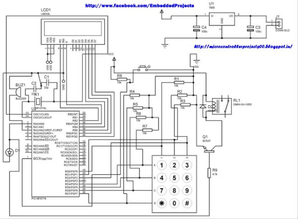
In this case, different approaches have to be made. The most popular one is to use synchronous serial data (requiring a “clock” and “data”) pin to load a serial-in/parallel-out shift register with the data bits and “R/S” pin information. The “E” Strobe Pin is driven directly by the microcontroller to latch in the data from the LCD. This is shown in the diagram below:

The project presented in this article is an enhancement of this circuit. By combining the shift register’s “Data Line” with the most significant bit of the shift register, the “E” Strobe can be implemented without resorting to a separate line for the function. The 1 K resistor and diode act as an “AND” gate. A schematic of the circuit is shown below.

The operation of the resistor/diode “AND” gate may not be immediately obvious. When the shift register bit is low, the diode pulls the connection to the “E” pin low. When the shift register bit is high, the diode will not cause any current flow from the connection at the “E” pin to the shift register. The resistor from “Data” to the “E” pin is a current limiting resistor. When the shift register bit is low and the data bit is high, then the current through the resistor will be limited to 5 mA (for a 5 Volt logic application). At the “Data” side of the resistor, the voltage will still be high, even though the diode is pulling the “E” pin low.

When both the “Data” line and the shift register bit are high, the “E” pin will be high. The “AND” circuit could be a TTL two input AND gate (such as a 7408), if you have an extra one available for your application. When I originally created this circuit, I used the same two transistor and two resistor circuit that I used for the 89C2051 emulator in “Programming and Customizing the 8051 Microcontroller”. I saw this “AND” equivalent circuit in an old copy of “Electronics Now” and found that it worked well in this application.

To load the shift register, it first has to be cleared to ensure that the “E” will not be strobed to the LCD inadvertently. This is done by first shifting in six “0”s to make sure that while the correct data is being loaded into the shift register, no “high” voltage level is passed to the “E” pin of the LCD.

Once this is done, the data can be shifted in. The diagram below shows how the shift register is initially cleared and then loaded with the data to be strobed (using “E”) into the LCD:


For more detail: 2-Wire LCD Interface using PIC16C84

The post 2-Wire LCD Interface using PIC16C84 appeared first on PIC Microcontroller.
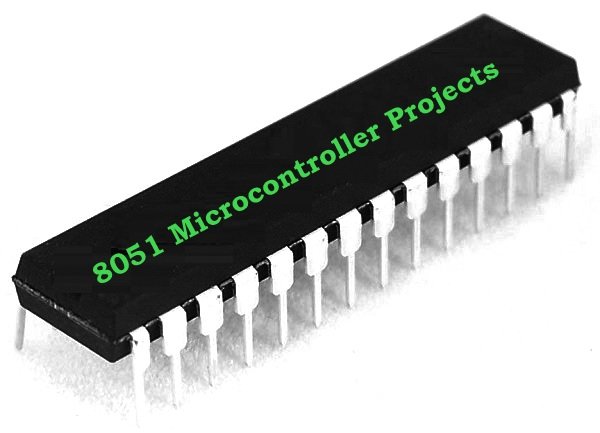
How to Interface LCD with PIC16F877A Slicker

$
0
0

PIC16F/18F Slicker Board

The PIC16F/18F Slicker board is specifically designed to help students to master the required skills in the area of embedded systems. The kit is designed in such way that all the possible features of the microcontroller will be easily used by the students. The kit supports in system programming (ISP) which is done through USB port.

Microchip’s PIC (PIC16F877A), PIC16F/18F Slicker Kit is proposed to smooth the progress of developing and debugging of various designs encompassing of High speed 8-bit Microcontrollers.

How to Interface LCD with PIC16F877A SlickerLCD (Liquid Crystal Display)

Liquid Crystal Display also called as LCD is very helpful in providing user interface as well as for debugging purpose. A liquid crystal display (LCD) is a flat panel display that uses the light modulating properties of liquid crystals (LCs). LCD Modules can present textual information to user.

Interfacing LCD

Fig. 1 shows how to interface the LCD to microcontroller. The 2×16 character LCD interface card with supports both modes 4-bit and 8-bit interface, and also facility to adjust contrast through trim pot. In 8-bit interface 11 lines needed to create 8-bit interface; 8 data bits (D0 – D7), three control lines, address bit (RS), read/write bit (R/W) and control signal (E).

nterfacing LCD with PIC16F877A

We now want to display a text in PIC16F/18F Slicker Board by using LCD module. In PIC16F/18F Slicker Board contains the LCD connections in a single header.

How to Interface LCD with PIC16F877A Slicker SchematicThe PIC16F/18F Slicker board has eleven numbers of LCD connections, connected with I/O Port lines (PORTE.0 – PORTE.3 && PORTD.0 – PORTD.7) to make LCD display.

Source Code

The Interfacing LCD with PIC16F877A program is very simple and straight forward, which display a text in 2 X 16 LCD modules. Some delay is occurring when a single command / data is executed.


For more detail: How to Interface LCD with PIC16F877A Slicker

The post How to Interface LCD with PIC16F877A Slicker appeared first on PIC Microcontroller.

How to implement free running counter in PIC16F84A using seven segment display

$
0
0

This post provides the implementation of free running counter ( using c language ) for PIC16F84A micro-controller. This code is written in such a way that, the counter starts from a value of ‘0’ ( displayed on the seven segment ) and then increments this value after every second. So, the seven segment display starts from ‘0’ and then displays ‘1’, ‘2’, ‘3’, ‘4’, ‘5’, ‘6’, ‘7’, ‘8’, ‘9’, ‘A’, ‘b’, ‘C’, ‘d’, ‘E’, and in the end ‘F’. After displaying ‘F’, counter starts from ‘0’ again and this pattern repeats forever.

PIC16F84A using seven segment display

The code and Proteus simulation is given in the ‘Downloads‘ section at the bottom of this page. It is assumed that you know how to make an LED blink with PIC16F84A micro-controller. If you don’t, then please read this post first.

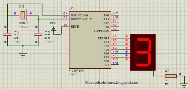
The following figure shows the circuit of free running counter in Proteus.

A crystal of 20 MHz is used here. You can use any crystal value from 0 to 20MHz with PIC16F84A. As we know that PIC16F84A microcontroller has an architecture which executes an instruction in 4 CPU cycles [1], hence this 20Mhz crystal makes this PIC16F84A run at 5.0 MIPS (Million of instructions per second).

PORTB is used here to connect PIC16F84A with the seven segment display. RB0 pin is attached with the ‘a’ segment of the seven segment display. Similarly, RB1 pin is connected with ‘b’ segment, RB2 pin is connected with ‘c’ segment and so on.

Common cathode seven segment display is used in this example. You can easily modify this circuit and code for the common anode seven segment display as well.

PIC16F84A using seven segment display schematic

Code

The following function is used in the code to display values on the seven segment display.

Downloads

Free running counter code using PIC16F84A was compiled in MPLAB v8.85 with HI-TECH C v9.83 compiler and simulation was made in Proteus v7.10. To download code and Proteus simulation click here.


For more detail: How to implement free running counter in PIC16F84A using seven segment display

The post How to implement free running counter in PIC16F84A using seven segment display appeared first on PIC Microcontroller.
RFID Based Attendance System – Circuit, Working, Source Code

$
0
0

Attendance in colleges is generally paper based which may sometimes cause errors. Taking attendance manually consumes more time. So the proposed attendance system uses RFID technology to take attendance. In this system, each student is issued an RFID tag. Controlling unit is in the institute. Whenever the card is placed near the reader, it will …

RFID Based Attendance System – Circuit, Working, Source Code Continue Reading

The post RFID Based Attendance System – Circuit, Working, Source Code appeared first on PIC Microcontroller.
Serial Data Received from PC and Displayed on 16×2 Using USART of Pic16f877 Microcontroller

$
0
0

Here is a simple tutorial on how to receive serial data from PC(Personal Computer) Hyperterminal and display it on 16×2 lcd using PIC16f877 microcontroller. Its not much difficult you just need to know how to use USART(Universal Syncronous-Asyncronous receiver transmitter) of PIC 16f877. Serial data is transmitted and recived by PC using DB-9 OR DB-25 …

Serial Data Received from PC and Displayed on 16×2 Using USART of Pic16f877 Microcontroller Continue Reading

The post Serial Data Received from PC and Displayed on 16×2 Using USART of Pic16f877 Microcontroller appeared first on PIC Microcontroller.
WHAT IS A PIC MICROCONTROLLER? WHAT CAN IT DO?

$
0
0

PIC microcontrollers ( Programmable Interface Controllers), are electronic circuits that can be programmed to carry out a vast range of tasks. They can be programmed to be timers or to control a production line and much more. They are found in most electronic devices such as alarm systems, computer control systems, phones, in fact almost …

WHAT IS A PIC MICROCONTROLLER? WHAT CAN IT DO? Continue Reading

The post WHAT IS A PIC MICROCONTROLLER? WHAT CAN IT DO? appeared first on PIC Microcontroller.
Frequency Counter by PIC16F628

Viewing all 253 articles
Browse latest View live


<script src="https://jsc.adskeeper.com/r/s/rssing.com.1596347.js" async> </script>