Quantcast
Channel: LCD Projects - PIC Microcontroller
Viewing all 253 articles
Browse latest View live

LCD DISPLAY FAN CONTROL CIRCUIT PIC16F84A PICBASIC PRO

$
0
0

This circuit and the microcontroller PIC16F84A DS18B20 temperature information is obtained using the temperature sensor. 16X2 LCD screen showing temperature information obtained from user-specified temperature is exceeded audible warning. The ambient temperature value drops to the desired level of… Electronics Projects, LCD Display Fan Control Circuit PIC16F84A Picbasic Pro “microchip projects, microcontroller projects, pic16f84 projects, picbasic pro examples,

LCD DISPLAY FAN CONTROL CIRCUIT PIC16F84A PICBASIC PRO

This circuit and the microcontroller PIC16F84A DS18B20 temperature information is obtained using the temperature sensor. 16X2 LCD screen showing temperature information obtained from user-specified temperature is exceeded audible warning. The ambient temperature value drops to the desired level of the fan keeps up. In addition to user-specified EEPROM heat value recorded in any power outages, loss of information is prohibited. Plus (+) and minus (-) buttons required for the operation of the fan allows you to set the temperature level.

PIC16F84A FAN CONTROL SCHEMATIC

PIC16F84A FAN CONTROL SCHEMATIC

PIC16F84A FAN CONTROL PCB TOP

PIC16F84A FAN CONTROL PCB TOP

PIC16F84A LCD Display Fan Control Circuit proteus isis simulaiton schematic proteus ares PCB and pic16f84 picbasic pro source code files

FILE DOWNLOAD LINK LIST (in TXT format): LINKS-3385.zip

Source: LCD DISPLAY FAN CONTROL CIRCUIT PIC16F84A PICBASIC PRO

The post LCD DISPLAY FAN CONTROL CIRCUIT PIC16F84A PICBASIC PRO appeared first on PIC Microcontroller.


8051 STOPWATCH CIRCUIT WITH LCD DISPLAY

$
0
0

Stopwatch Circuit 8051 on behalf of the programming of integrated compiler program that is used too much in the present case. You are left with only the easiest to use and most advantageous for you to choose. 8051, which… Electronics Projects, 8051 Stopwatch Circuit with Lcd Display “8051 example, avr project, keil example, microcontroller projects,

Stopwatch Circuit 8051 on behalf of the programming of integrated compiler program that is used too much in the present case. You are left with only the easiest to use and most advantageous for you to choose. 8051, which can be programmed Uvısıon2 KEIL compiler is without a doubt the most advanced ones, I think.

8051 STOPWATCH SCHEMATIC

8051 Stopwatch Circuit proteus isis simulation and 8051 keil source code files:

FILE DOWNLOAD LINK LIST (in TXT format): LINKS-3342.zip

Source: 8051 STOPWATCH CIRCUIT WITH LCD DISPLAY

The post 8051 STOPWATCH CIRCUIT WITH LCD DISPLAY appeared first on PIC Microcontroller.

8051 ADC0808 LCD DISPLAY VOLTMETER

$
0
0

ADC0808 analog / digital converter of the 8 analog inputs (IN0-IN7) and 8-bit digital output (OUT0-OUT7) are available. Entries will be transferred to the digital output of the converter which converted to 3-bit ADD, ADD B, and C address… Electronics Projects, 8051 ADC0808 Lcd Display Voltmeter “8051 example, avr project, keil example, microcontroller projects,

8051 ADC0808 LCD DISPLAY VOLTMETER

ADC0808 analog / digital converter of the 8 analog inputs (IN0-IN7) and 8-bit digital output (OUT0-OUT7) are available. Entries will be transferred to the digital output of the converter which converted to 3-bit ADD, ADD B, and C address ADD is decided according to the tips. ADC0808 to run the ADC clock (Clock) at the end of about 10 KHz-1280 KHz frequency values ​​of the hour mark, which should be applied. VREF (+) terminal of the maximum amplitude of the analog signal to be sampled Vref (-) to indicate the minimum value of the signal to be sampled is used for. Applications Vref (-) usually bağlanır.start soil, OE (Output Enable) and the EOC (End of Conversion) are end-end control of the ADC0808.

8051 VOLTMETER SCHEMATIC

8051 VOLTMETER SCHEMATIC

ADC0808 8051 Lcd Display Voltmeter keil source code and proteus isis simulation files:

FILE DOWNLOAD LINK LIST (in TXT format): LINKS-3295.zip

Source: 8051 ADC0808 LCD DISPLAY VOLTMETER

The post 8051 ADC0808 LCD DISPLAY VOLTMETER appeared first on PIC Microcontroller.

AT89C51 LCD DISPLAY FREQUENCYMETER PROJECT

$
0
0

Frequency in all matters relating to the definition based on frequency is required. In the same way the numeric (digital) Frequency frequency to do the same as the description of the circuit should be implemented. Frequency: 1 frequency is… Electronics Projects, AT89C51 LCD display Frequencymeter Project “8051 example, avr project, keil example, microcontroller projects,

AT89C51 LCD DISPLAY FREQUENCYMETER PROJECT

Frequency in all matters relating to the definition based on frequency is required. In the same way the numeric (digital) Frequency frequency to do the same as the description of the circuit should be implemented.

Frequency: 1 frequency is called the number of periods per second.

Period: a wave of complete rotations made ​​to peryotlu (to speed). Completed the transfer periods are called waves.

Pulse: A pulse is called a half periods. One positive in the first periods, including the other two pulses are negative.

Frequency Unit: HERTZ defined. There are submultiples of value, but there are multiples of the base.

AT89C51 FREQUENCYMETER SCHEMATIC

AT89C51 FREQUENCYMETER SCHEMATIC

AT89C51 LCD display Frequencymeter circuit schematic, proteus isis simulation and keil soruce code files;

FILE DOWNLOAD LINK LIST (in TXT format): LINKS-3230.zip

Source: AT89C51 LCD DISPLAY FREQUENCYMETER PROJECT

The post AT89C51 LCD DISPLAY FREQUENCYMETER PROJECT appeared first on PIC Microcontroller.

PIC18F452 128X64 GRAPHIC LCD ANIMATION EXAMPLE

$
0
0

PIC18F452 microcontroller and the proton ide I built using compiler consists of a total of 17 square 128X64 gif animation graphics portrayed on the screen I share my work with you. Gif file using Adobe ImageReady and Photoshop in… Electronics Projects, PIC18F452 128X64 Graphic LCD Animation Example “microchip projects, microcontroller projects, picbasic pro examples,

PIC18F452 128X64 GRAPHIC LCD ANIMATION EXAMPLE

PIC18F452 microcontroller and the proton ide I built using compiler consists of a total of 17 square 128X64 gif animation graphics portrayed on the screen I share my work with you. Gif file using Adobe ImageReady and Photoshop in 17 different 128X64 and bmp file after converting it to a resolution of 72dpi I gave in addition bmp2asm files include files into a proton brought on compiler. In addition to the file and in the Proteus simulation source code

PIC18F452 GRAPHIC LCD ANIMATION PICBASIC PRO

PIC18F452 GRAPHIC LCD ANIMATION PICBASIC PRO

PIC18F452 128X64 GLCD Animation picbasic pro source code and proteus isis simulation schematic files:

FILE DOWNLOAD LINK LIST (in TXT format): LINKS-2516.zip

Source: PIC18F452 128X64 GRAPHIC LCD ANIMATION EXAMPLE

The post PIC18F452 128X64 GRAPHIC LCD ANIMATION EXAMPLE appeared first on PIC Microcontroller.

8051 PS2 KEYBOARD WITH LCD WRITING TEXT

$
0
0

PS / 2 protocol used text via a keyboard microcontroller applications that perform printing text on the LCD The goal here Text via keyboard microcontroller to print text on the LCD. Through keyboard microcontroller contained in a code corresponding… Electronics Projects, 8051 PS2 Keyboard with LCD Writing Text “8051 example, avr project, keil example, microcontroller projects,

8051 PS2 KEYBOARD WITH LCD WRITING TEXT

PS / 2 protocol used text via a keyboard microcontroller applications that perform printing text on the LCD

The goal here Text via keyboard microcontroller to print text on the LCD. Through keyboard microcontroller contained in a code corresponding to each keystroke is generated. About scan code ASCII code is used as code corresponds microcontroller and LCD is switched to the found and processed. Circuit connectors are shown below:

8051 PS2 KEYBOARD CIRCUIT DIAGRAM

Analyzing Source code “t_lcd.h” and tarama.h named header files have been used. Contains functions that are required to drive LCD “t_lcd.h” header file is given below. “Tarama.h” header file for the PS / 2 keyboard scan codes corresponding to each of the keys are included.

Keil and proteus isis ares files to the 8051 PS2 Keyboard project:

FILE DOWNLOAD LINK LIST (in TXT format): LINKS-2413.zip

Source: 8051 PS2 KEYBOARD WITH LCD WRITING TEXT

The post 8051 PS2 KEYBOARD WITH LCD WRITING TEXT appeared first on PIC Microcontroller.

AT89C51 ANIMATED BMP GRAPHIC LCD DISPLAY

$
0
0

AT89C51 microcontroller controlled Animated BMP project usnig Graphic LCD Display 128×64 project keil source code and proteus isis simulation schematic files Graphic LCD Animated BMP Schematic project files: FILE DOWNLOAD LINK LIST (in TXT format): LINKS-2374.zip author: Cihangir Kılıç… Electronics Projects, AT89C51 Animated BMP Graphic LCD Display “8051 example, avr project, keil example, microcontroller projects, 

AT89C51 microcontroller controlled Animated BMP project usnig Graphic LCD Display 128×64 project keil source code and proteus isis simulation schematic files

GRAPHIC LCD ANIMATED BMP SCHEMATIC

GRAPHIC LCD ANIMATED BMP SCHEMATIC

project files:

FILE DOWNLOAD LINK LIST (in TXT format): LINKS-2374.zip

Source: AT89C51 ANIMATED BMP GRAPHIC LCD DISPLAY

The post AT89C51 ANIMATED BMP GRAPHIC LCD DISPLAY appeared first on PIC Microcontroller.

PIC16F877 NOKIA 3310 LCD DISPLAY IR REMOTE RC5 CONTROL

$
0
0

Remote control circuit nokia 3310 LCD screen used in the PIC16F877 microcontroller can be used rc5 protocol detailed frequency information is also given on other control systems. Printed circuit board pcb eagle and schema files as well as resources… Electronics Projects, PIC16F877 Nokia 3310 LCD Display IR Remote RC5 Control “ccs c examples, microchip projects, microcontroller projects, pic16f877 projects,

PIC16F877 NOKIA 3310 LCD DISPLAY IR REMOTE RC5 CONTROL

Remote control circuit nokia 3310 LCD screen used in the PIC16F877 microcontroller can be used rc5 protocol detailed frequency information is also given on other control systems. Printed circuit board pcb eagle and schema files as well as resources available in CCS C code through 011_28.c, 16F877_mb.h, nokia_3310_mb.c, ir_read_mb.c, 24256_mb.c

PIC16F877 INFRARED REMOTE CONTROL

NEC SIRCS JAPAN RC5 SAMSUNG compatible, multiprotocol infrared remote control Replaces up to 6 existing remote controls into one. With manual learning function, LED display and/or LCD. 2V6-3V2, low power (sleep function) More protocols will be added later if needed (DENON-DAEWOO,MOTOROLA,RECS80.)

PIC16LF877-04/L (4Mhz PLCC Package), 24LC256 EEPROM (low power), 74HC148 encoder (SMD), optional Nokia 3310 graphic LCD (LPH-7779), IR LED, 5 optional LEDs, TSOP34836 IR receiver (low voltage)

PIC16F877 INFRARED REMOTE CONTROL

Source: www.techdesign.be PIC16F877 Nokia 3310 LCD Display IR Remote RC5 Control alternative link:

FILE DOWNLOAD LINK LIST (in TXT format): LINKS-2273.zip

Source: PIC16F877 NOKIA 3310 LCD DISPLAY IR REMOTE RC5 CONTROL

The post PIC16F877 NOKIA 3310 LCD DISPLAY IR REMOTE RC5 CONTROL appeared first on PIC Microcontroller.


AT89C51 8051 GRAPHIC LCD ANIMATION

$
0
0

GLCD Animation circuit voltage is applied to the currently displayed map of Turkey comes first. Subsequently, the Turkish flag and a picture of Mustafa Kemal Atatürk, the next step is to come. Art world will begin to come after … Electronics Projects, AT89C51 8051 Graphic LCD Animation ” 8051 example, apr project, keil example, microcontroller projects,

AT89C51 8051 GRAPHIC LCD ANIMATION

GLCD Animation circuit voltage is applied to the currently displayed map of Turkey comes first. Subsequently, the Turkish flag and a picture of Mustafa Kemal Atatürk, the next step is to come. Art world will begin to come after arrival.

Circuit operation: Graphic LCD as the most important feature point-based study. So, as in LCDs text and text can be printed as well as shape can be drawn. Half-P2 as data output port ayarlanmıştır.p1_0 end graphic LCD’s CS1, CS2 end P1_1 port is connected to the graphic LCD. Graphic Lcd structure is divided into 2 sections, including the right and left.

LCD ANIMATION SCHEMATIC

LCD ANIMATION SCHEMATIC

8051 Graphic LCD Animation proteus isis simulation schematic keil source code :

FILE DOWNLOAD LINK LIST ( in TXT format ): LINKS-1359.zip

Source: AT89C51 8051 GRAPHIC LCD ANIMATION

The post AT89C51 8051 GRAPHIC LCD ANIMATION appeared first on PIC Microcontroller.

0-25V ​​2.5A DIGITAL POWER SUPPLY CIRCUIT LCD DISPLAY PIC16F873P

$
0
0

Digital power supply circuit with microcontroller pic16f873p conducted and current sensing, power transistors (tip142) is used in the control LM324 op amp. LCD display showing information on the current and voltage source project pic code (asm, hex) and with… Electronics Projects, 0-25V ​​2.5A Digital Power Supply Circuit LCD Display PIC16F873P “microchip projects, microcontroller projects, pic assembly example,

0-25V ​​2.5A DIGITAL POWER SUPPLY CIRCUIT LCD DISPLAY PIC16F873P

Digital power supply circuit with microcontroller pic16f873p conducted and current sensing, power transistors (tip142) is used in the control LM324 op amp. LCD display showing information on the current and voltage source project pic code (asm, hex) and with eagle pcb files have drawn diagrams. For boxing writers have used an old AT power supply box.

PIC16F873 PICMICRO DIJITAL POWER SUPPLY

PIC16F873 PICMICRO DIJITAL POWER SUPPLY

Laboratory electronics may be missing a source of power with which all our projects and developments, here we have a variable Source 0-25V 2.5 A microcontroller power supply digital

Source: esteca55.com.ar Digital Power Supply Circuit pcb PIC16F873 pic assembly source code alternative link:

FILE DOWNLOAD LINK LIST (in TXT format): LINKS-1259.zip

Source: 0-25V ​​2.5A DIGITAL POWER SUPPLY CIRCUIT LCD DISPLAY PIC16F873P

The post 0-25V ​​2.5A DIGITAL POWER SUPPLY CIRCUIT LCD DISPLAY PIC16F873P appeared first on PIC Microcontroller.

Intelligent access control based on STONE TFT LCD and ESP32

$
0
0

Brief Introduction

Smart home is becoming more and more common with the development of technology, this article will focus on the security aspects of the intelligent access control project.

This article uses STONE’s touch screen to send commands to the MCU to control the relay and MFRC522 module.

The principle of card reading: by driving the RFID-RC522 module, identify the ID card ID close to the ID card, and then determine whether the ID exists in the database of the word typical, ID is the typical value of the word, if the existence of the verification through, and then print out the corresponding name, and then drive the electromagnetic lock in the same way.

Required materials

Realized function

1. card registration.

2. username and password registration.

3. card swipe to unlock the electronic lock.

4. User name and password to unlock the electronic lock.

The main hardware Description

RFID Module

This module can be directly loaded into various reader modules. It utilizes a voltage of 3.3V, through the SPI interface with simply a few wires. Directly connected with a CPU motherboard, the module can work in a stable and reliable manner as a distance card reader.

STONE STWI070WT-01 display

The STWI070WT-01 has been conceived as TFT monitor & Touch controller. It includes processor, control program, driver, flash memory, RS232/RS422/RS485/TTL/LAN port, Wi-Fi/Bluetooth, touch screen, power supply etc., so it is a whole display system based on the powerful & easy operating system, which can be controlled by Any MCU.

Connection diagram

GUI design

Code sharing

Main.py

import mfrc522

import time

import _thread

from os import uname

from machine import Pin, UART

#from pyb import UART

#import machine

suos = Pin(32,Pin.OUT)

uart2 = UART(2, baudrate=115200, rx=16,tx=17,timeout=10)

ESP32_HSPI_CLOCK = 14

ESP32_HSPI_SLAVE_SELECT = 15

ESP32_HSPI_MISO = 12

ESP32_HSPI_MOSI = 13

ESP32_MFRC522_RST = 5

rx3 = []

rx_name = []

user_id_flag = False

password_flag = False

temp_id = ”

temp_mima = ”

personnel_id = {‘zbw’:[236,230,169,47],’lbw’:[19,165,93,4]}

personnel_ps = {‘zbw’:’zbw3366′,’lbw’:’lbwnb’}

admin_password = (‘yyds’)

button_cmd = [16,1]

edit1_cmd = [16,112]

edit2_cmd = [16,113]

edit3_cmd = [16,114]

if uname()[0] == ‘esp32’:

                rdr = mfrc522.MFRC522(ESP32_HSPI_CLOCK, ESP32_HSPI_MOSI, ESP32_HSPI_MISO, ESP32_MFRC522_RST, ESP32_HSPI_SLAVE_SELECT)

def do_write():

                try:

                                (stat, tag_type) = rdr.request(rdr.REQIDL)

                                if stat == rdr.OK:

                                                (stat, raw_uid) = rdr.anticoll()

                                                if stat == rdr.OK:

                                                                print(“New card detected”)

                                                                print(”  – tag type: 0x%02x” % tag_type)

                                                                print(”  – uid : 0x%02x%02x%02x%02x” % (raw_uid[0], raw_uid[1], raw_uid[2], raw_uid[3]))

                                                                print(“”)

                                                                if rdr.select_tag(raw_uid) == rdr.OK:

                                                                                key = [0xFF, 0xFF, 0xFF, 0xFF, 0xFF, 0xFF]

                                                                                if rdr.auth(rdr.AUTHENT1A, 8, key, raw_uid) == rdr.OK:

                                                                                                stat = rdr.write(8, b”\x00\x53\x00\x54\x00\x4F\x00\x4E\x00\x45\x0a\x0b\x0c\x0d\x0e\x0f”)

                                                                                                rdr.stop_crypto1()

                                                                                                if stat == rdr.OK:

                                                                                                                print(“Data written to card”)

                                                                                                else:

                                                                                                                print(“Failed to write data to card”)

                                                                                else:

                                                                                                print(“Authentication error”)

                                                                else:

                                                                                print(“Failed to select tag”)

                except KeyboardInterrupt:

                                print(“write error”)

def do_read():

                while True:

                                try:

                                                (stat, tag_type) = rdr.request(rdr.REQIDL)

                                                if stat == rdr.OK:

                                                                (stat, raw_uid) = rdr.anticoll()

                                                                if stat == rdr.OK:

                                                                                print(“New card detected”)

                                                                                print(”  – tag type: 0x%02x” % tag_type)

                                                                                print(”  – uid   : 0x%02x%02x%02x%02x” % (raw_uid[0], raw_uid[1], raw_uid[2], raw_uid[3]))

                                                                                print (raw_uid[0], raw_uid[1], raw_uid[2], raw_uid[3])

                                                                                print(“”)

                                                                                if rdr.select_tag(raw_uid) == rdr.OK:

                                                                                                key = [0xFF, 0xFF, 0xFF, 0xFF, 0xFF, 0xFF]

                                                                                                if rdr.auth(rdr.AUTHENT1A, 8, key, raw_uid) == rdr.OK:

                                                                                                                print(“Address 8 data: %s” % rdr.read(8))

                                                                                                                for ps in personnel_id:

                                                                                                                                if raw_uid[0:4:1] == personnel_id.get(ps):

                                                                                                                                                suos.value(1)

                                                                                                                                                print(ps)

                                                                                                                                                uart_write(ps, *raw_uid[0:4:1])

                                                                                                                                                time.sleep(3)

                                                                                                                                                uart2.sendbreak()

                                                                                                                                                break

                                                                                                                rdr.stop_crypto1()

                                                                                                                time.sleep(3)

                                                                                                                suos.value(0)

                                                                                                else:

                                                                                                                print(“Authentication error”)

                                                                                else:

                                                                                                print(“Failed to select tag”)

                                                if uart2.any()>1:

                                                                rx2 = []

                                                                data_name2 = ”

                                                                bin_data = uart2.read(40)

                                                                uart2.sendbreak()

                                                                rx1 = list(bin_data)

                                                                for item in rx1:

                                                                                rx2.append(chr(item))

                                                                print(rx2)

                                                                if rx1[3:5:1] == button_cmd:

                                                                                data_name_len = rx1[6] – 1

                                                                                data_name = rx2[7:data_name_len+7:1]

                                                                                data_name2 = ”.join(data_name)

                                                                                print(data_name2)

                                                                                if data_name2 == ‘back3’:

                                                                                                return

                                except KeyboardInterrupt:

                                                print(“read error”)

def do_read2 (idd):

                print(idd)

                while True:

                                try:

                                                (stat, tag_type) = rdr.request(rdr.REQIDL)

                                                if stat == rdr.OK:

                                                                (stat, raw_uid) = rdr.anticoll()

                                                                if stat == rdr.OK:

                                                                                print(“New card detected”)

                                                                                print(”  – tag type: 0x%02x” % tag_type)

                                                                                print(”  – uid   : 0x%02x%02x%02x%02x” % (raw_uid[0], raw_uid[1], raw_uid[2], raw_uid[3]))

                                                                                print (raw_uid[0], raw_uid[1], raw_uid[2], raw_uid[3])

                                                                                print(“”)

                                                                                if rdr.select_tag(raw_uid) == rdr.OK:

                                                                                                key = [0xFF, 0xFF, 0xFF, 0xFF, 0xFF, 0xFF]

                                                                                                if rdr.auth(rdr.AUTHENT1A, 8, key, raw_uid) == rdr.OK:

                                                                                                                print(“Address 8 data: %s” % rdr.read(8))

                                                                                                                personnel_id[idd] = raw_uid[0:4:1]

                                                                                                                uart_write3(*raw_uid[0:4:1])

                                                                                                                rdr.stop_crypto1()

                                                                                                else:

                                                                                                                print(“Authentication error”)

                                                                                else:

                                                                                                print(“Failed to select tag”)

                                                if uart2.any()>1:

                                                                rx2 = []

                                                                data_name2 = ”

                                                                bin_data = uart2.read(40)

                                                                uart2.sendbreak()

                                                                rx1 = list(bin_data)

                                                                for item in rx1:

                                                                                rx2.append(chr(item))

                                                                if rx1[3:5:1] == button_cmd:

                                                                                data_name_len = rx1[6] – 1

                                                                                data_name = rx2[7:data_name_len+7:1]

                                                                                data_name2 = ”.join(data_name)

                                                                                print(data_name2)

                                                                if data_name2 == ‘back1’:

                                                                                return

                                except KeyboardInterrupt:

                                                print(“read error”)

def uart_write(text, *ids):

#              print(text, *ids)

                uart2.write(‘ST<{“cmd_code”:”set_text”,”type”:”label”,”widget”:”cardname1″,”text”:”‘+str(text)+'”}>ET’)

                uart2.write(‘ST<{“cmd_code”:”set_text”,”type”:”label”,”widget”:”cardid1″,”text”:”‘+str(ids)+'”}>ET’)

                uart2.write(‘ST<{“cmd_code”:”set_visible”,”type”:”widget”,”widget”:”lock1″,”visible”:true}>ET’)

                time.sleep(3)

                uart2.write(‘ST<{“cmd_code”:”set_text”,”type”:”label”,”widget”:”cardname1″,”text”:”””}>ET’)

                uart2.write(‘ST<{“cmd_code”:”set_text”,”type”:”label”,”widget”:”cardid1″,”text”:”””}>ET’)                 uart2.write(‘ST<{“cmd_code”:”set_visible”,”type”:”widget”,”widget”:”lock1″,”visible”:false}>

ET’)

def uart_write2(text,text2):

                uart2.write(‘ST<{“cmd_code”:”set_text”,”type”:”label”,”widget”:”cardid”,”text”:”‘+text+'”}>ET’)

                time.sleep(3)

                uart2.write(‘ST<{“cmd_code”:”set_text”,”type”:”label”,”widget”:”cardid”,”text”:”‘+text2+'”}>ET’)

                uart2.write(‘ST<{“cmd_code”:”set_text”,”type”:”label”,”widget”:”edit2″,”text”:”””}>ET’)

def uart_write3(*id2):

                uart2.write(‘ST<{“cmd_code”:”set_text”,”type”:”label”,”widget”:”cardid”,”text”:”‘+str(id2)+'”}>ET’)

                time.sleep(3)

                uart2.write(‘ST<{“cmd_code”:”set_text”,”type”:”label”,”widget”:”cardid”,”text”:”””}>ET’)

def uart_write4(text,text2):

                uart2.write(‘ST<{“cmd_code”:”set_text”,”type”:”label”,”widget”:”login”,”text”:”‘+text+'”}>ET’)

                time.sleep(1)

                uart2.write(‘ST<{“cmd_code”:”set_text”,”type”:”label”,”widget”:”login”,”text”:”‘+text2+'”}>ET’)

                time.sleep(1)

                uart2.write(‘ST<{“cmd_code”:”set_text”,”type”:”label”,”widget”:”edit3″,”text”:”””}>ET’)

                uart2.write(‘ST<{“cmd_code”:”set_text”,”type”:”label”,”widget”:”edit4″,”text”:”””}>ET’)

                uart2.write(‘ST<{“cmd_code”:”set_text”,”type”:”label”,”widget”:”edit7″,”text”:”””}>ET’)

def uart_write5():

                uart2.write(‘ST<{“cmd_code”:”set_text”,”type”:”label”,”widget”:”cardid”,”text”:”‘+str(id2)+'”}>ET’)

                time.sleep(3)

                uart2.write(‘ST<{“cmd_code”:”set_text”,”type”:”label”,”widget”:”cardid”,”text”:”””}>ET’)

def card_zhuce():

                while True:

                                if uart2.any():

                                                user_id = ”

                                                password = ”

                                                rx2 = []

                                                rx_num = 0

                                                bin_data = uart2.read(40)

                                                uart2.sendbreak()

                                                rx1 = list(bin_data)

                                                for item in rx1:

                                                                rx2.append(chr(item))

                                                                rx_num += 1

                                                data_end = rx_num-5

                                                data_id_st = rx2[8:13:1]

                                                data_id_st2 = ”.join(data_id_st)

                                                print(data_id_st2)

                                                if data_id_st2 == ‘edit1’:

                                                                data_id_st3 = rx2[15:data_end:1]

                                                                data_id_st4 = ”.join(data_id_st3)

                                                                print(data_id_st4)

                                                                if data_id_st4 != ”:

                                                                                name = True

                                                elif data_id_st2 == ‘edit2’:

                                                                data_id_st5 = rx2[15:data_end:1]

                                                                data_id_st6 = ”.join(data_id_st5)

                                                                if data_id_st6 == admin_password:

                                                                                admin = True

                                                                                uart_write2(‘Verification passed!’,’Please place the card!’)

                                                                                do_read2(data_id_st4)

                                                                                return

def mima_zuce():

                temp_id3 = ”

                temp_mima3 = ”

                while True:

                                if uart2.any():

                                                user_id = ”

                                                password = ”

                                                rx2 = []

                                                rx_num = 0

#                                              data_end = 0

                                                bin_data = uart2.read(40)

                                                uart2.sendbreak()

                                                rx1 = list(bin_data)

                                                for item in rx1:

                                                                rx2.append(chr(item))

                                                                rx_num += 1

#                                                              if (rx2[rx_num] == ‘T’) and (rx2[rx_num-1] == ‘E’) and (rx2[rx_num-2] == ‘>’):

#                                                                              break

                                                data_end = rx_num-5

                                                data_id_st = rx2[8:13:1]

                                                data_id_st2 = ”.join(data_id_st)

                                                print(data_id_st2)

                                                if rx1[3:5:1] == button_cmd:

                                                                data_name_len = rx1[6] – 1

                                                                data_name = rx2[7:data_name_len+7:1]

                                                                data_name2 = ”.join(data_name)

                                                                print(data_name2)

                                                                if data_name2 == ‘back2’:

                                                                                return

                                                if data_id_st2 == ‘edit3’:

                                                                data_id_st3 = rx2[15:data_end:1]

                                                                data_id_st4 = ”.join(data_id_st3)

                                                                print(data_id_st4)

                                                                user_id_flag = True

                                                                temp_id3 = data_id_st4

#                                                              personnel_ps[temp_id] = raw_uid[0:4:1]

                                                elif data_id_st2 == ‘edit4’:

                                                                data_id_st5 = rx2[15:data_end:1]

                                                                data_id_st6 = ”.join(data_id_st5)

                                                                print(data_id_st6)

#                                                              if personnel_ps.get(temp_id) == data_id_st6:

                                                                password_flag = True

                                                                temp_mima3 = data_id_st6

#                                                                              personnel_ps[temp_id] = password_flag

#                                              print(rx2,user_id_flag,password_flag)

                                                elif data_id_st2 == ‘edit7’:

                                                                data_id_st5 = rx2[15:data_end:1]

                                                                data_id_st6 = ”.join(data_id_st5)

                                                                if (data_id_st6 == admin_password) and (password_flag == True) and (user_id_flag == True):

                                                                                admin = True

                                                                                personnel_ps[temp_id3] = temp_mima3

                                                                                password_flag = False

                                                                                user_id_flag = False

                                                                                uart_write4(‘Verification passed!’,’login was successful!’)

def password_loin():

                temp_id2 = ”

                temp_mima = ”

                while True:

                                if uart2.any():

                                                user_id = ”

                                                password = ”

                                                rx2 = []

                                                rx_num = 0

#                                              data_end = 0

                                                bin_data = uart2.read(40)

                                                uart2.sendbreak()

                                                rx1 = list(bin_data)

                                                for item in rx1:

                                                                rx2.append(chr(item))

                                                                rx_num += 1

#                                                              if (rx2[rx_num] == ‘T’) and (rx2[rx_num-1] == ‘E’) and (rx2[rx_num-2] == ‘>’):

#                                                                              break

                                                data_end = rx_num-5

                                                data_id_st = rx2[8:13:1]

                                                data_id_st2 = ”.join(data_id_st)

                                                print(data_id_st2)

                                                if rx1[3:5:1] == button_cmd:

                                                                data_name_len = rx1[6] – 1

                                                                data_name = rx2[7:data_name_len+7:1]

                                                                data_name2 = ”.join(data_name)

                                                                print(data_name2)

                                                                if data_name2 == ‘back4’:

                                                                                return

                                                if data_id_st2 == ‘edit5’:

                                                                data_id_st3 = rx2[15:data_end:1]

                                                                data_id_st4 = ”.join(data_id_st3)

                                                                print(data_id_st4)

                                                                if data_id_st4 in personnel_ps:

                                                                                user_id_flag = True

                                                                                temp_id2 = data_id_st4

                                                elif data_id_st2 == ‘edit6’:

                                                                data_id_st5 = rx2[15:data_end:1]

                                                                data_id_st6 = ”.join(data_id_st5)

                                                                print(data_id_st6)

                                                                print(temp_id2)

                                                                print(personnel_ps)

                                                                if personnel_ps.get(temp_id2) == data_id_st6:

                                                                                password_flag = True

#                                              print(rx2,user_id_flag,password_flag)

                                                                                print(user_id_flag,password_flag)

                                                                                if (password_flag == True) and (user_id_flag == True):

                                                                                                uart_write(temp_id2,temp_id2)

                                                                                                password_flag = False

                                                                                                user_id_flag = False

                                                                                                suos.value(1)

                                                                                                uart2.write(‘ST<{“cmd_code”:”set_visible”,”type”:”widget”,”widget”:”lock2″,”visible”:true}>ET’)

                                                                                                uart2.write(‘ST<{“cmd_code”:”set_text”,”type”:”label”,”widget”:”edit5″,”text”:”””}>ET’)

                                                                                                uart2.write(‘ST<{“cmd_code”:”set_text”,”type”:”label”,”widget”:”edit6″,”text”:”””}>ET’)

                                                                                                time.sleep(3)

#                                                                                              uart_write(‘student’,”)

                                                                                                suos.value(0)

                                                                                                uart2.write(‘ST<{“cmd_code”:”set_visible”,”type”:”widget”,”widget”:”lock2″,”visible”:false}>ET’)

                                                                                                uart2.sendbreak()

while True:

                if uart2.any()>1:

                                rx2 = []

                                data_name2 = ”

                                bin_data = uart2.read(40)

#                              time.sleep(1)

                                uart2.sendbreak()

#                              time.sleep(1)

                                rx1 = list(bin_data)

                                for item in rx1:

                                                rx2.append(chr(item))

                                print(rx2)

                                if rx1[3:5:1] == button_cmd:

                                                data_name_len = rx1[6] – 1

                                                data_name = rx2[7:data_name_len+7:1]

                                                data_name2 = ”.join(data_name)

                                                print(data_name2)

                                                if data_name2 == ‘card1’:

                                                                card_zhuce()

                                                elif data_name2 == ‘password1’:

                                                                mima_zuce()

                                                elif data_name2 == ‘card2’:

                                                                do_read()

                                                elif data_name2 == ‘password2’:

                                                                password_loin()

MFRC522.py

from machine import Pin, SPI

from os import uname

class MFRC522:

                OK = 0

                NOTAGERR = 1

                ERR = 2

                REQIDL = 0x26

                REQALL = 0x52

                AUTHENT1A = 0x60

                AUTHENT1B = 0x61

                def __init__(self, sck, mosi, miso, rst, cs):

                                self.sck = Pin(sck, Pin.OUT)

                                self.mosi = Pin(mosi, Pin.OUT)

                                self.miso = Pin(miso)

                                self.rst = Pin(rst, Pin.OUT)

                                self.cs = Pin(cs, Pin.OUT)

                                self.rst.value(0)

                                self.cs.value(1)

                                board = uname()[0]

                                if board == ‘WiPy’ or board == ‘LoPy’ or board == ‘FiPy’:

                                                self.spi = SPI(0)

                                                self.spi.init(SPI.MASTER, baudrate=1000000, pins=(self.sck, self.mosi, self.miso))

                                elif board == ‘esp32’:

                                                self.spi = SPI(baudrate=100000, polarity=0, phase=0, sck=self.sck, mosi=self.mosi, miso=self.miso)

                                                self.spi.init()

                                else:

                                                raise RuntimeError(“Unsupported platform”)

                                self.rst.value(1)

                                self.init()

                def _wreg(self, reg, val):

                                self.cs.value(0)

                                self.spi.write(b’%c’ % int(0xff & ((reg << 1) & 0x7e)))

                                self.spi.write(b’%c’ % int(0xff & val))

                                self.cs.value(1)

                def _rreg(self, reg):

                                self.cs.value(0)

                                self.spi.write(b’%c’ % int(0xff & (((reg << 1) & 0x7e) | 0x80)))

                                val = self.spi.read(1)

                                self.cs.value(1)

                                return val[0]

                def _sflags(self, reg, mask):

                                self._wreg(reg, self._rreg(reg) | mask)

                def _cflags(self, reg, mask):

                                self._wreg(reg, self._rreg(reg) & (~mask))

                def _tocard(self, cmd, send):

                                recv = []

                                bits = irq_en = wait_irq = n = 0

                                stat = self.ERR

                                if cmd == 0x0E:

                                                irq_en = 0x12

                                                wait_irq = 0x10

                                elif cmd == 0x0C:

                                                irq_en = 0x77

                                                wait_irq = 0x30

                                self._wreg(0x02, irq_en | 0x80)

                                self._cflags(0x04, 0x80)

                                self._sflags(0x0A, 0x80)

                                self._wreg(0x01, 0x00)

                                for c in send:

                                                self._wreg(0x09, c)

                                self._wreg(0x01, cmd)

                                if cmd == 0x0C:

                                                self._sflags(0x0D, 0x80)

                                i = 2000

                                while True:

                                                n = self._rreg(0x04)

                                                i -= 1

                                                if ~((i != 0) and ~(n & 0x01) and ~(n & wait_irq)):

                                                                break

                                self._cflags(0x0D, 0x80)

                                if i:

                                                if (self._rreg(0x06) & 0x1B) == 0x00:

                                                                stat = self.OK

                                                                if n & irq_en & 0x01:

                                                                                stat = self.NOTAGERR

                                                                elif cmd == 0x0C:

                                                                                n = self._rreg(0x0A)

                                                                                lbits = self._rreg(0x0C) & 0x07

                                                                                if lbits != 0:

                                                                                                bits = (n – 1) * 8 + lbits

                                                                                else:

                                                                                                bits = n * 8

                                                                                if n == 0:

                                                                                                n = 1

                                                                                elif n > 16:

                                                                                                n = 16

                                                                                for _ in range(n):

                                                                                                recv.append(self._rreg(0x09))

                                                else:

                                                                stat = self.ERR

                                return stat, recv, bits

                def _crc(self, data):

                                self._cflags(0x05, 0x04)

                                self._sflags(0x0A, 0x80)

                                for c in data:

                                                self._wreg(0x09, c)

                                self._wreg(0x01, 0x03)

                                i = 0xFF

                                while True:

                                                n = self._rreg(0x05)

                                                i -= 1

                                                if not ((i != 0) and not (n & 0x04)):

                                                                break

                                return [self._rreg(0x22), self._rreg(0x21)]

                def init(self):

                                self.reset()

                                self._wreg(0x2A, 0x8D)

                                self._wreg(0x2B, 0x3E)

                                self._wreg(0x2D, 30)

                                self._wreg(0x2C, 0)

                                self._wreg(0x15, 0x40)

                                self._wreg(0x11, 0x3D)

                                self.antenna_on()

                def reset(self):

                                self._wreg(0x01, 0x0F)

                def antenna_on(self, on=True):

                                if on and ~(self._rreg(0x14) & 0x03):

                                                self._sflags(0x14, 0x03)

                                else:

                                                self._cflags(0x14, 0x03)

                def request(self, mode):

                                self._wreg(0x0D, 0x07)

                                (stat, recv, bits) = self._tocard(0x0C, [mode])

                                if (stat != self.OK) | (bits != 0x10):

                                                stat = self.ERR

                                return stat, bits

                def anticoll(self):

                                ser_chk = 0

                                ser = [0x93, 0x20]

                                self._wreg(0x0D, 0x00)

                                (stat, recv, bits) = self._tocard(0x0C, ser)

                                if stat == self.OK:

                                                if len(recv) == 5:

                                                                for i in range(4):

                                                                                ser_chk = ser_chk ^ recv[i]

                                                                if ser_chk != recv[4]:

                                                                                stat = self.ERR

                                                else:

                                                                stat = self.ERR

                                return stat, recv

                def select_tag(self, ser):

                                buf = [0x93, 0x70] + ser[:5]

                                buf += self._crc(buf)

                                (stat, recv, bits) = self._tocard(0x0C, buf)

                                return self.OK if (stat == self.OK) and (bits == 0x18) else self.ERR

                def auth(self, mode, addr, sect, ser):

                                return self._tocard(0x0E, [mode, addr] + sect + ser[:4])[0]

                def stop_crypto1(self):

                                self._cflags(0x08, 0x08)

                def read(self, addr):

                                data = [0x30, addr]

                                data += self._crc(data)

                                (stat, recv, _) = self._tocard(0x0C, data)

                                return recv if stat == self.OK else None

                def write(self, addr, data):

                                buf = [0xA0, addr]

                                buf += self._crc(buf)

                                (stat, recv, bits) = self._tocard(0x0C, buf)

                                if not (stat == self.OK) or not (bits == 4) or not ((recv[0] & 0x0F) == 0x0A):

                                                stat = self.ERR

                                else:

                                                buf = []

                                                for i in range(16):

                                                                buf.append(data[i])

                                                buf += self._crc(buf)

                                                (stat, recv, bits) = self._tocard(0x0C, buf)

                                                if not (stat == self.OK) or not (bits == 4) or not ((recv[0] & 0x0F) == 0x0A):

                                                                stat = self.ERR

                                return stat

The post Intelligent access control based on STONE TFT LCD and ESP32 appeared first on PIC Microcontroller.

Homemade MPC Style MIDI Controller

$
0
0

1.0 INTRODUCTION


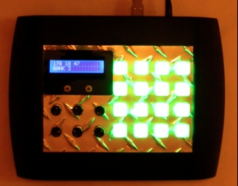
 I decided to build and design a midi controller which is used to send commands to a computer running a DAW(digital audio workstation)  to control different parameters within it. The DAW I used is called Ableton Live. There are 16 button pads and 6 potentiometers on the front of the unit. Depending on which DAW is used, you can assign the potentiometers to control parameters like track volume, track reverb, and any other effects applied to a track. There is also a dock on the side which has 10 more analog channels to connect more potentiometers and allow for future expansion of other projects and ideas.  The buttons can be used to launch loops, or you can play it just as you would play a regular piano or keyboard.  You will be able to change the bank of notes that the buttons send to the computer using bank up and bank down button on the front panel. There is a total of 128 notes (or 128 values)  you can play on the buttons and you can bank up 16 notes at a time meaning 8 banks. There are also RGB LEDs’ under the buttons to indicate what bank you are currently on. There is also an LCD display displays what value you are sending to the computer and indicates the bank number.

1.1 Midi Overview


Midi allows you to control virtual instruments within a audio recording program. For example you can assign a piano to a track and control the notes of the virtual piano using a midi controller.  A midi command is consists of 3 bytes. The first byte is a status byte. It tells the computer what type of action it will be performing. For example a common status byte would be  the decimal value 144 which means note on. This is then followed by two data bytes; the next one being which note to turn on.  0 is the lowest note and 128 is the highest.  The last byte would be how loud you want that note to sound.  This is called velocity. 0 would be the quietest and 128 would be the loudest.   If you want to control things like volume or any other parameters you can send what is called a control change command. This is only two bytes. The first byte would tell the computer which control change you are wanting to control. For example sending the decimal value 16 would be initiated a control change on channel 1.   The next byte is the value between 0 and 128  which is sent to the computer. You assign which parameter is controls within the program.

2.0 PCB AND HARDWARE SETUP


There are 3 PCBs’ which I have designed which make the operation of this midi controller possible; the main PCB(Figure 2.0), the RGB driver(Figure 3.0-yellow), and  the analog channel expansion port(4.0-yellow). There are 3 units I have used that are bought online; the MIDI to USB converter(Figure 4.0-purple), the LCD screen(Figure 3.0-purple), and the button pad PCB(Figure 3.0-purple).

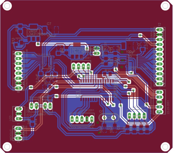
The main PCB holds the microcontroller I used, and two ADC chips. The microcontroller I used is a PIC18F2550, and the two ADCs’ I used are LTC2309s’.  If you refer to figure 2.0, you can see the PIC placed in the center and I have placed the two ADC’s on either end of the PCB. The reason I did this was because of the location I have mounted the PCB within the enclosure. The 6 onboard potentiometers are to the left of the PCB and the ADC extension port is to the right of the main PCB.  Since each ADC has 8 channels, I have set it up so  IC2 uses 6 of its channels for the onboard potentiometers, and then the extra two  ADC channels  are added to the ADC extension port. 
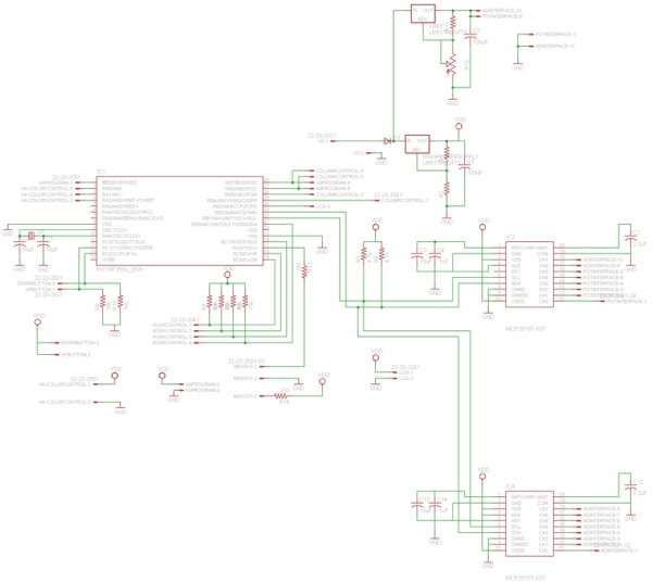
If you refer to the main PCB schematic in step 5, you will note that I have used two voltage regulators for this design. IC3 is set to regulate the voltage at 5 volts. This voltage is used to power the chips, LCD, and button pad LEDs’. The other voltage regulator, IC5, is an adjustable reference voltage for the potentiometers and ADC channels.  This is adjusted using a small surface mount potentiometer located directly beside it. There is also a diode in series at the input of these voltage regulators to keep anything from being damaged if the input voltage was accidently reversed. I made sure the diode was rated high enough to handle the current.  Located around the PIC are various connectors used for connecting to the button pad and LEDs’. The function of each pin will be discussed in a later section. To the right of the PIC are the connectors used for connecting to the analog channel expansion port and the programming port. The reason I have the programming port on the same PCB as the ADC extension port is I want to be able to reprogram the PIC without having to remove the lid of the unit. To get access to it, the side panel simply needs to be removed as shown in figure 5.0.
The LED driver PCB I designed is mounted directly beneath the button pad PCB(Figure 3.0).  If you refer to the schematic in step 4 this PCB enables me to control all the LEDs at the same time.  The connection from this board to the main PCB has 5 pins; VDD, GND,  and 3 LED control pins. Each of these control pins is connected directly to the input of the mosfet on the driver board which controls all the LEDs of that color. One mosfet controls all the red LEDs, one for all the green LEDs, and one for all the blue LEDs.

Step 1: Program Operation.

3.0 PROGRAM OPERATION


The following section will discuss how the program works.  Section 3.1 will go over the initialization part of the code which happens before the main loop. Once the program enters the main loop is calls out to 4 different functions: potread, keypress,  bankchange, and RGB. Sections 3.2, 3.3, 3.4, and 3.5 will discuss these functions separately.  Please refer to the code in step 6.

3.1 Initialization


Any microcontroller needs to be configured first before it enters a main program loop.  This includes setting up the direction of the pins, putting the correct values in any of the control registers, and defining the main clock that the microcontroller is going to be using.  The first step of my program was to set up the config registers.   These registers typically control things like the watchdog timer, any master clear reset pins, brown out detect, and oscillator configurations. In this particular example I set it up so that a 20Mhz external oscillator crystal is used as the main clock for the PIC.  The PIC has internal oscillators and can run up to 8Mhz, but due to the speed of the midi data, I needed to run the microcontroller at a higher speed in order to avoid any data errors.  Note the location of the oscillator on the main PCB board layout in section 7.1. I soldered the crystal directly beneath the board so it is not visible in figure 2.0.
The next register I configured was the RCSTA and TXSTA registers. These registers are responsible for controlling hardware serial commands. The reason I used hardware serial commands, as opposed to software serial for sending the midi commands, is because I am sending the data to the midi converter board at 31250 baud.  I tried sending the data first using software commands only, and I was getting errors and the computer was receiving data that had missing bits and missing pieces of information.  The hardware serial port has an internal buffer used for directing the flow of data and is therefore more reliable.  The only limitation of using the hardware serial commands is you are restricted to using only certain pins on the microcontroller where as if you send software commands, you can use any available pin you want.   The LCD I used only required the data to be sent at 9600 baud, so I any command I sent to the LCD was software serial commands.
I then set up the pins that were going to be used to control the LTC2309 chips.  These chips are controlled using I2C commands so only two pins are needed to control the two chips.
After this I defined all the global variables used in the program. I then configured the direction of the pins but loading the correct bytes into the TRISA, TRISB, and TRISC registers on the PIC.  Loading a zero defines the pin of that port to an output. Loading a one, defines it as an input. For example: if I load the value 00000001 in into the TRISB register,  Pin zero on PORTB would be an input while pins one through seven are defined as outputs.
Since the PIC also has onboard ADCs’ I needed to disable those so that’s the next thing I did.  The LCD display then is turned on and an intro screen is displayed.  The software serial command is a function built into Picbasic Pro which is the compiler I used.   Anytime I want to issue a software serial command, I need to specify the pin I want to send the command on, the baud rate, and the data that I want to send.  I found out how to control the LCD through its data sheet. 
The buttons then cycle through the different colors.  The purpose of this is to make sure everything is connected properly.  If all the colors are displayed I know the RGB LEDs are connected correctly. The program then enters the main loop.

3.2 Potread


Since there are 8 channels on each LTC2309, I set up the program so all 8 channels of IC2 are read in one for loop, and all 8 channels of IC4 are read in another for loop.  Since these chips are controlled using I2C commands only two pins are used.  One is a clock pin, which runs a 100Khz, and the other pin is a bi-directional pin, which is used to send and receive data.

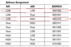
In order to read the analog value from any given channel, you need to tell the ADC what channel you want to read therefore before you read any channel you must first send two bytes of information to the chip. The first byte the microcontroller sends to the ADC is the address frame. There are two pins on the LTC2309, which you can configure to set the address.  By setting the AD1 pin, and AD0 pin to either high, low, or floating, you can get up to 8 different addresses, meaning you can connect up to 8 different LTC2309s’ on one I2C bus.  If you refer to Figure 6.0 you can view the different configurations.  I’ve indicated which address’ I am using. 7 bits are used as the address, and  the LSB(Bit 0) is used to indicate weather it is a read command or write command.  Setting this bit to one prepares the ADC for a read command and setting it to zero sets it to a write command.

The following byte sent to the ADC is a 6 bit “Din” word.  This is responsible for channel configuration.  See Figure 8.0 for Din configurations. I’ve highlighted the different words I have used.  In my program, the S/D bit is always set because I am doing single ended measurements.  The UNI bit is also always set because I am only using the chip in unipolar mode.  Figure 7.0 is the timing diagram for a write command included in the data sheet.

Next the ADC sends the analog value to the microcontroller. However, any time any information exchanged from the ADC to the microcontroller, you must still send the address frame, except the LSB in the address frame is changed to one, meaning it is a read command.   The 12 bit analog value is sent in two bytes.  Figure 9.0 is the format of the data comes in. I read the analog value into two different variables. One variable holds the 8 most significant bits, and the other byte holds the 4 least significant bits of the variable.  However the least significant bits are siting 4 places to the left in that variable, and the 4 bits to the right are just zeroes. In order to get this value into a useable form, I shift the 8 most significant bits 4 places to the left. I am able to do this since the variable I am using is a 16 bit word.  I then shift the variable with the 4 least significant bits 4 spots to the right.  These two values are then or’ed together and the result is a 16 bit variable with a 12 bit analog value.  However I still have to scale the value down since a midi control signal value is only one byte. The max ADC value is 4095 in decimal, and therefore needs to be scaled down to 128. To do this I multiply the ADC value by 4095 then divide is by 128.  I have another variable, which I use to save the previous ADC value. When the loop comes around again it checks if the new ADC value has changed. If it changed more than a certain threshold value, then it sends a midi signal with the new ADC value.  If it is below this value, it skips it all together and continues to read the next channel.  I save the un-scaled value, so this threshold is 50.  I had to choose a value that was large enough to be above the noise, but not be so large that the analog values sent to the midi controller are really far away from each other, thus giving a choppy sound. A midi control command is a series of 3 bytes. The first byte specifies that it is a control command that is being sent. The second byte is which channel the control command is being sent.  The last byte is the analog value.    So for example, lets say within my music software I assign a volume on a certain channel to accept incoming midi signals from channel 16.  As I turn the potentiometer, the midi controller is continuously sending these 3 bytes at a very fast rate.  First two bytes stay the same every time these bytes are sent but the last value will be changing. The idea is you want this value to move up or down in small increments. The increments that it changes by is the threshold value  was discussed earlier. I increment the channel by 1, after each loop, so all the potentiometers are writing to their own midi channel. This loop is then continued 7 more times for that ADC chip. I continue a different loop another 8 times to read the values from the other ADC chip. The only difference between the two loops is the address I use to communicate with the chip, and the channel numbers that are being updated.

Step 2:

3.3 Keypress


“Scanning” is the process I used to multiplex the button pad so I wouldn’t have to use 16 pins on the microcontroller for 16 buttons. Instead I only had to use 8 pins. If you refer to step 4 I’ve included the schematic for the button pad I bought from sparkfun electronics and have indicated the signal path of each pin on the button pad PCB. As you can see there are separate pins for controlling the LEDs and controlling the buttons. The LED control pins will be discussed in a later section.
The microcontroller is set it up so all the columns are outputs and all the rows are inputs. If you refer to the button pad schematic, I start by setting the first column (which is RB4 on the pic) to zero. I set the rest of the columns to 1(RB5,RB6,RB7).  The program then checks the state of all the rows at the same time(RC4,RC5,RC7,RC0). The program pauses for 1 millisecond and checks those pins again. Since switches and buttons often bounce, this causes unwanted ripples on the signal, so we eliminate this with a process called de-bouncing. If the values from the two checks are equal then that means it was a valid button press on that column and not a bounce.  The program then enters a for loop, which checks the state of each of the rows. If a button is pressed on that column, it is read as a zero on the corresponding row since the column is set to zero. Since each of the pins on the rows has a 10k pull-up resistor(not shown on button pad schematic),  if a button is not pressed that row pin will be read as a 1. 
Once a button press is detected on that column it sends a 3 byte midi message over the hardware serial port on the PIC.  The first byte is 0x92 which the computer detects as a channel 4 note on message. The second byte is which note is to be turned on, which can be anywhere between 0 and 127. Since I am using a for loop to check each of the rows I am using the for loop variable “i” to indicate which note I want on.  Since I am also using 8 banks of notes(128 notes total)  I add it to the current bank variable which is “c”. The bank switch process will be further discussed in section 3.4. The last byte is the velocity which also can be anywhere between 0 and 127, but for all the buttons I set that value to 100.  The next line of code then sends the same commands in ascii text to an LCD over a microcontroller pin I configured for software serial out.
The microcontroller also needs to detect when a note is released because it needs to send another command to turn that same note off. Within the same for loop this is done by sending the same 3 bytes except the last byte(velocity), is set to zero which turns that note off. If this command not sent, that note would stay on indefinitely, even if that button was released. 
Up until this point we have only checked the status, and sent commands for the 4 buttons on the first column. This whole process is repeated 3 more times, one for each column.  In the next for loop I set the next column to zero and set the rest to 1, and do the same for the remaining columns. 


3.4 Bank Change


Since there are 128 different midi notes that can be sent as  a midi command I wanted to be able to make full use of all of them, so I added the ability to bank between groups of 16 notes at a time. To do this I added two push buttons on the front panel beneath the LCD(see Figure 1.0).  To bank up, I polled the input of the pin on the microcontroller I set up as the input for banking up. Since I set up these microcontroller inputs with a pull-down resistor I checked for a low to high transition when the switch connects to VDD. When that transition was detected, I added one to the variable “j”.  I set it up so once “j” was more than 8 it reset back to zero. I also wanted the ability to save the bank on the non-volatile eeprom so if for what ever reason I have to remove the power to re-arrange cables the midi controller boots up and automatically sets itself back to the bank it was on before it was powered off.  I also found that if I was holding a note and pressed one of the bank buttons at the same time,  the midi controller lost track of which note was being pressed so that note would never turn off. To fix this I made a for loop which turns off all of the notes at the same time anytime I bank up or down.  I used the same code for the bank down button except instead of adding one to “j” I subtracted one from “j” and has it reset to 8 if it went below 1.   I set it up so “j” as a global variable and is used throughout different sections of the program.  
At the end of this function, I check what value j is and set the variable  “c” accordingly. “c” enables the midi controller to bank up 16 notes at a time by adding it to whichever keypad number you are pressing.  For example if I want midi note number 35 on, I need to go to bank 3.   “c” is added to which key number I am pressing. So if I am pressing button number 3 on the keypad, the midi controller adds the value “c”, which is in this case is 32.


3.5 RGB


I set aside 3 pins on the microcontroller to control all the RGB LEDs’.  RA0 controls all the red LEDs’, RA1 controls all the green LEDs’ and RA2 controls all the blue.  Each pin controls all the LEDs’ by connecting to the gate on a MOSFET located on the LED driver board(See step 4). The LEDs’ had to be driven this way because the current required to drive all the LEDs’ exceeded the microctrollers current sourcing abilities.
This RGB function in the program basically checks what bank of notes the midi controller is in by checking the value of the variable “j”.  To get the different colors I simply combined different sets of colors together. For example to get the color purple, I turn on red and blue at the same time by setting RA0 and RA2 to high and setting RA1 to low.

Step 3:

4.0 ESTHETICS


4.1 Enclosure


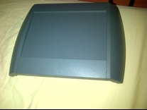
I purchased the enclosure from OKW(www.okw.com), a  company in the states which manufactures various types of enslosures and project boxes. I first downloaded the autoCAD drawing of the enclosure I wanted to purchase so I could check the dimensions to make sure it would fit a project of this scale.  I also used this autoCAD drawing to find the dimensions and spacing of the plastic mounting stand-offs built into it so it would match with the PCBs’. Figure 10.0 is a picture of what it looked like before I did any modification to it. I then painted it and used a dremel to cut a hole big enough to fit the face plate I was going to design(Figure 11.0).

4.2 Front Panel

To design the front panel I used AutoCAD. I found the drawing of the button pad I purchased and used that to make sure the holes and mounting screws were properly spaced apart so buttons could be pressed without having them stick. I also found a drawing of the LCD and did the same thing.  When my panel design was done, I purchased some diamond plate aluminum from a hardware store(Figure 12.0) and had it machined using a CNC mill I had access to(Figure 13.0)

Step 4: Schematics and Board Layouts

Images are in the following order:

-Main PCB schematic
– Analog Channel Expansion Port Schematic
-Button Pad Schematic
– RGB Driver Schematic

Step 5: Board Layouts

Images are in the following order:

-Main PCB Layout
-Analog Channel Expansion Port Board Layout
-Button Pad Board Layout
-RGB Driver Board Layout

Step 6: The Code.

‘****************************************************************
‘*  Name    : UNTITLED.BAS                                      *
‘*  Author  : Matthew Reid                                      *
‘*  Notice  : Copyright (c) 2012 [select VIEW…EDITOR OPTIONS] *
‘*          : All Rights Reserved                               *
‘*  Date    : 9/5/2012                                          *
‘*  Version : 1.0                                               *
‘*  Notes   :                                                   *
‘*          :                                                   *
‘****************************************************************
pause 300
include “modedefs.bas”

#CONFIG
__CONFIG _CONFIG1L, _PLLDIV_5_1L   & _CPUDIV_OSC1_PLL2_1L & _USBDIV_2_1L
__CONFIG _CONFIG1H, _FOSC_HS_1H & _FCMEN_ON_1H  & _IESO_ON_1H
__CONFIG _CONFIG2L, _PWRT_ON_2L & _BOR_ON_2L & _BORV_3_2L & _VREGEN_OFF_2L
__CONFIG _CONFIG2H, _WDT_ON_2H & _WDTPS_256_2H
__CONFIG _CONFIG3H, _MCLRE_OFF_3H & _PBADEN_OFF_3H
__CONFIG _CONFIG4L, _STVREN_ON_4L & _LVP_OFF_4L & _XINST_OFF_4L & _DEBUG_OFF_4L
#endconfig
define OSC 20


OSCCON = %00001000

‘set up hardware serial port
define HSER_RCSTA 90H
define HSER_TXSTA 24H
define HSER_BAUD 31250


‘i2c ports
SDA var PORTB.2
SCL var PORTB.1

‘button variables

‘column 1 variables
buttonval1 var byte
bouncecheck1 var byte
buttonstate1 var bit[4]i var byte
value1 var byte

‘column 2 variables
buttonval2 var byte
bouncecheck2 var byte
buttonstate2 var bit[4]value2 var byte

‘column 3 variables
buttonval3 var byte
bouncecheck3 var byte
buttonstate3 var bit[4]value3 var byte

‘column 4variables
buttonval4 var byte
bouncecheck4 var byte
buttonstate4 var bit[4]value4 var byte

‘bankchange variable
upstate var bit
downstate var bit
j var byte: j = 1
c var byte


‘variables for a to d  (IC2)
one var byte[8]two var byte[8]three var word[8] :three = 0
threshold var word: threshold = 50
prevpotval var byte[8]
prevadval var word[8]currentadval var word [8]
‘variables for a to d  (IC1)
one1 var byte[8]two1 var byte[8]three1 var word[8] :three = 0

prevpotval1 var byte[8]
prevadval1 var word[8]currentadval1 var word [8]


‘port direction
trisa = %00000000
trisb = %00000001
trisc = %10110110

‘enable RC4 and RC5
ucon.3 = 0
ucfg.3 = 1

‘disable internal A to D
adcon0 = %00111100
adcon1 = %00001111


‘turn on lcd and set brightness to max
pause 1000
serout PORTB.3, N9600, [$1b,$2a,$FF]

serout PORTB.3,N9600,[$1b,$30]serout PORTB.3,N9600,[$1b,$2a,200]serout PORTB.3,N9600,[$1b,$46]
serout PORTB.3,N9600,[$fe,$80]serout PORTB.3,N9600,[“Midi Pad v1_1”]serout PORTB.3,N9600,[$fe,$c0]serout PORTB.3,N9600,[“Matt Reid  2012”]
‘intro flash

‘red
porta.0 = 1
porta.1 = 0
porta.2 = 0
pause 400
‘green
porta.0 = 0
porta.1 = 1
porta.2 = 0
pause 400
‘blue
porta.0 = 0
porta.1 = 0
porta.2 = 1
pause 400
‘purple
porta.0 = 1
porta.1 = 0
porta.2 = 1
pause 400
‘white
porta.0 = 1
porta.1 = 1
porta.2 = 1
pause 400
‘cyan
porta.0 = 0
porta.1 = 1
porta.2 = 1
pause 400

‘_________________________


‘read bank from eeprom
read 5, j

mainloop:
gosub bankchange  
gosub keypress
gosub potread
gosub RGB

goto mainloop


bankchange:

‘bank up
if portc.2 = 1 & upstate = 1 then
j = j + 1
    if j > 8 then
    j = 1
    endif

    ‘clear all notes
    for i = 0 to 128
    hserout[$92, i, 0]    next i
    ‘write bank change to eeprom
    write 5,j
upstate = 0 
endif  
if portc.2 = 0 & upstate = 0 then
upstate = 1
endif

‘bank down
if portc.1 = 1 & downstate = 1 then
j = j – 1
    if j < 1 then
    j = 8
    endif
    ‘clear all notes
    for i = 0 to 128
    hserout[$92, i, 0]    next i
    ‘write bank change to eeprom
    write 5,j

downstate = 0 
endif  
if portc.1 = 0 & downstate = 0 then
downstate = 1
endif

‘display bank
serout PORTB.3, N9600, [$Fe, $c0]serout PORTB.3, N9600, [“BANK”, ” “, #j, ”         “]
if j = 1 then
c = 0
endif

if j = 2 then
c = 16
endif

if j = 3 then
c = 32
endif

if j = 4 then
c = 48
endif

if j = 5 then
c = 64
endif

if j = 6 then
c = 80
endif

if j = 7 then
c = 96
endif

if j = 8 then
c = 112
endif


return


potread:
‘adc potentiometer stuff——————————————————


‘read ic2
for i = 1 to 8
    three[i] = 0

        if i = 1 then
        i2cwrite SDA, SCL, %00010000 , [ %10001100]        endif
        if i = 2 then
        i2cwrite SDA, SCL, %00010000 , [ %11001100]        endif
        if i = 3 then
        i2cwrite SDA, SCL, %00010000 , [ %10011100]        endif
        if i = 4 then
        i2cwrite SDA, SCL, %00010000 , [ %11011100]        endif
        if i = 5 then
        i2cwrite SDA, SCL, %00010000 , [ %10101100]        endif
        if i = 6 then
        i2cwrite SDA, SCL, %00010000 , [ %11101100]        endif
        if i = 7 then
        i2cwrite SDA, SCL, %00010000 , [ %10111100]        endif
        if i = 8 then
        i2cwrite SDA, SCL, %00010000 , [ %11111100]        endif
    ‘this pause is important to keep the adc from jumping around
    pause 4

    i2cread SDA, SCL, %00010001, [one[i], two[i]]


    three[i] = one[i] | three[i]

    three[i] = three[i]<<4
    two[i] = two[i]>>4
    three[i] = two[i] | three[i]    currentadval[i] = three[i]    ‘pause 10

    three[i] = three[i] * 128
    three[i] = div32 4095   

    if abs(currentadval[i] – prevadval[i]) >= threshold then
         hserout[$B2, 13+i, three[i]]         prevpotval[i] = three[i]         prevadval[i] =  currentadval[i]         ‘display a to d value
    serout PORTB.3, N9600, [$Fe, $80]        serout PORTB.3, N9600, [#178, ” “, #(13+i), ” “,#three[i], ”           “]    endif    
next i

‘read ic1
for i = 1 to 8
    three1[i] = 0

        if i = 1 then
        i2cwrite SDA, SCL, %00010100 , [ %10001100]        endif
        if i = 2 then
        i2cwrite SDA, SCL, %00010100 , [ %11001100]        endif
        if i = 3 then
        i2cwrite SDA, SCL, %00010100 , [ %10011100]        endif
        if i = 4 then
        i2cwrite SDA, SCL, %00010100 , [ %11011100]        endif
        if i = 5 then
        i2cwrite SDA, SCL, %00010100 , [ %10101100]        endif
        if i = 6 then
        i2cwrite SDA, SCL, %00010100 , [ %11101100]        endif
        if i = 7 then
        i2cwrite SDA, SCL, %00010100 , [ %10111100]        endif
        if i = 8 then
        i2cwrite SDA, SCL, %00010100 , [ %11111100]        endif

    ‘this pause is important to keep the adc from jumping around
    pause 4

    i2cread SDA, SCL, %00010101, [one1[i], two1[i]]


    three1[i] = one1[i] | three1[i]

    three1[i] = three1[i]<<4
    two1[i] = two1[i]>>4
    three1[i] = two1[i] | three1[i]    currentadval1[i] = three1[i]    ‘pause 10

    three1[i] = three1[i] * 128
    three1[i] = div32 4095   

    if abs(currentadval1[i] – prevadval1[i]) >= threshold then
         hserout[$B2, 13+i, three1[i]]         prevpotval1[i] = three1[i]         prevadval1[i] =  currentadval1[i]         ‘display a to d value
    serout PORTB.3, N9600, [$Fe, $80]        serout PORTB.3, N9600, [#178, ” “, #(21+i), ” “,#three1[i], ”           “]    endif    
next i


return


keypress:

‘button code
‘set column 1——————————————————————–
portb.4 = 0
portb.5 = 1
portb.6 = 1
portb.7 = 1

buttonval1 = 0
bouncecheck1 = 0


buttonval1.0 = portc.4
buttonval1.1 = portc.5
buttonval1.2 = portc.7
buttonval1.3 = portb.0

pause 1

bouncecheck1.0 = portc.4
bouncecheck1.1 = portc.5
bouncecheck1.2 = portc.7
bouncecheck1.3 = portb.0


if buttonval1 = bouncecheck1 then

for i = 0 to 3  ‘ Count from 0 to 3

   value1 = buttonval1 >> i
    if value1.0 = 1 &  buttonstate1[i] = 1 then
    hserout[$92, c + i, 0]    serout PORTB.3, N9600, [$Fe, $80]    serout PORTB.3, N9600, [#146,” “, #(c + i),” “, #0, ”           “]    buttonstate1[i] = 0
    endif

    if value1.0 = 0 & buttonstate1[i] = 0 then
    hserout[$92, c + i, 100]    serout PORTB.3, N9600, [$Fe, $80]    serout PORTB.3, N9600, [#146,” “, #(c + i),” “, #100, ”           “]    buttonstate1[i] = 1
    endif

next i

endif


‘set column 2——————————————————————–
portb.4 = 1
portb.5 = 0
portb.6 = 1
portb.7 = 1

buttonval2 = 0
bouncecheck2 = 0


buttonval2.0 = portc.4
buttonval2.1 = portc.5
buttonval2.2 = portc.7
buttonval2.3 = portb.0

pause 1

bouncecheck2.0 = portc.4
bouncecheck2.1 = portc.5
bouncecheck2.2 = portc.7
bouncecheck2.3 = portb.0


if buttonval2 = bouncecheck2 then

for i = 0 to 3  ‘ Count from 0 to 3

   value2 = buttonval2 >> i
    if value2.0 = 1 &  buttonstate2[i] = 1 then
    hserout[$92, c+4+i, 0]    serout PORTB.3, N9600, [$Fe, $80]    serout PORTB.3, N9600, [#146,” “, #(c+4+i),” “, #0, ”           “]    buttonstate2[i] = 0
    endif

    if value2.0 = 0 & buttonstate2[i] = 0 then
    hserout[$92, c+4+i, 100]    serout PORTB.3, N9600, [$Fe, $80]    serout PORTB.3, N9600, [#146,” “, #(c+4+i),” “, #100, ”           “]    buttonstate2[i] = 1
    endif

next i

endif

‘set column 3——————————————————————–
portb.4 = 1
portb.5 = 1
portb.6 = 0
portb.7 = 1

buttonval3 = 0
bouncecheck3 = 0


buttonval3.0 = portc.4
buttonval3.1 = portc.5
buttonval3.2 = portc.7
buttonval3.3 = portb.0

pause 1

bouncecheck3.0 = portc.4
bouncecheck3.1 = portc.5
bouncecheck3.2 = portc.7
bouncecheck3.3 = portb.0


if buttonval3 = bouncecheck3 then

for i = 0 to 3  ‘ Count from 0 to 3

   value3 = buttonval3 >> i
    if value3.0 = 1 &  buttonstate3[i] = 1 then
    hserout[$92, c+8+i, 0]    serout PORTB.3, N9600, [$Fe, $80]    serout PORTB.3, N9600, [#146,” “, #(c+8+i),” “, #0, ”           “]    buttonstate3[i] = 0
    endif

    if value3.0 = 0 & buttonstate3[i] = 0 then
    hserout[$92, c+8+i, 100]    serout PORTB.3, N9600, [$Fe, $80]    serout PORTB.3, N9600, [#146,” “, #(c+8+i),” “, #100, ”           “]    buttonstate3[i] = 1
    endif

next i

endif


‘set column 4——————————————————————–
portb.4 = 1
portb.5 = 1
portb.6 = 1
portb.7 = 0

buttonval4 = 0
bouncecheck4 = 0


buttonval4.0 = portc.4
buttonval4.1 = portc.5
buttonval4.2 = portc.7
buttonval4.3 = portb.0

pause 1

bouncecheck4.0 = portc.4
bouncecheck4.1 = portc.5
bouncecheck4.2 = portc.7
bouncecheck4.3 = portb.0


if buttonval4 = bouncecheck4 then

for i = 0 to 3  ‘ Count from 0 to 3

   value4 = buttonval4 >> i
    if value4.0 = 1 &  buttonstate4[i] = 1 then
    hserout[$92, c+12+i, 0]    serout PORTB.3, N9600, [$Fe, $80]    serout PORTB.3, N9600, [#146,” “, #(c+12+i),” “, #0, ”           “]    buttonstate4[i] = 0
    endif

    if value4.0 = 0 & buttonstate4[i] = 0 then
    hserout[$92, c+12+i, 100]    serout PORTB.3, N9600, [$Fe, $80]    serout PORTB.3, N9600, [#146,” “, #(c+12+i),” “, #100, ”           “]    buttonstate4[i] = 1
    endif

next i

endif

return


RGB:

if j = 1 then
‘yellow
porta.1 = 0
pauseus 200


porta.0 = 1
porta.1 = 1
porta.2 = 0
endif

if j = 2 then
‘red
porta.0 = 1
porta.1 = 0
porta.2 = 0
endif

if j = 3 then
‘green
porta.0 = 0
porta.1 = 1
porta.2 = 0
endif

if j = 4 then
‘blue
porta.0 = 0
porta.1 = 0
porta.2 = 1
endif

if j = 5 then
‘purple
porta.0 = 1
porta.1 = 0
porta.2 = 1
endif

if j = 6 then
‘white
porta.0 = 1
porta.1 = 1
porta.2 = 1
endif

if j = 7 then
‘cyan
porta.0 = 0
porta.1 = 1
porta.2 = 1
endif

if j = 8 then
‘blue
porta.0 = 0
porta.1 = 0
porta.2 = 1
endif
return

Source: Homemade MPC Style MIDI Controller

The post Homemade MPC Style MIDI Controller appeared first on PIC Microcontroller.

Realtime OS / LCD on $12 Discovery Board

$
0
0

One day I had a college professor getting ready to teach us students a powerful mathematical trick in EE101 – mesh circuit analysis I think.  Before he got started he said, “Today, my students, I give you a BIG gun.”  It got our attention and I remember the quote, but sadly, I’d be hard pressed to do mesh analysis today.

Today, my Instructible readers, I give you BIG guns!

For all you hardcore hot-shot embedded software programmers, time to step up to the next level by learning how to use an embedded realtime OS on your next project.  Not only do you get a priority based preemptive realtime OS, you also get all the goodies that go along with a realtime embedded OS like:  Tasks, Queues, binary semaphores, counting semaphores, recursive semaphores and mutexes for communication and synchronization between tasks, or between tasks and interrupts.  Gives me goose-bumps just thinking about it!  All this software power comes by way of FreeRTOS which has been around a long time.

Oh, and the hardware we’re gonna run this on makes my head spin.  We’re not talking little a Pic or Atmel micro.  No, no, we’re gonna run this OS on a new 24MHz 32 Bit ARM® Cortex™-M3 from ST Micro.  The folks at ST Micro have made a development board, called the STM32 VL Discovery (VL is short for value line), available for $12 dollars!  They are probably selling the board at a loss.  For comparison, this board is about 1/3 the cost of a standard Arduino board.

The 24MHz STM32F100RBT6B micro that is used on the Discovery board is probably the slowest they sell.  Most of these chips run much faster!  However, the chip itself is not overly expensive – Digi-Key carriers the chip for $3.50 on orders over 100 pieces.  For $3.50 you get 128k flash and 8k RAM – no EEPROM needed since the micro can write to its own flash.

Below are the specs right off Mouser’s web page for the STM32F100RBT6B chip:

  • Core:                                              ARM Cortex M3
  • Data Bus Width:                             32 bit
  • Program Memory Type:                 Flash
  • Program Memory Size:                  128 KB
  • Data RAM Size:                              8 KB
  • Interface Type:                                I2C, SPI, USART
  • Maximum Clock Frequency:            24 MHz
  • Number of Programmable I/Os:       51
  • Number of Timers:                          6
  • Operating Supply Voltage:              2 V to 3.6 V
  • Maximum Operating Temperature:  + 85 C
  • Package / Case:                               LQFP-64
  • 3rd Party Development Tools:          EWARM, EWARM-BL, MDK-ARM, RL-ARM, ULINK2
  • Development Tools By Supplier:      STM32100B-EVAL
  • Minimum Operating Temperature:    – 40 C
  • On-Chip ADC:                                  12 bit, 16 Channel
  • On-Chip DAC:                                  12 bit, 2 Channel

Just in case you think the ARM is not good for small projects, I did another search on Digi-Key and turned up an even less expensive ARM chip from NXP.  The NXP micro (Digi-Key part number 568-5142-ND) is another ARM Cortex-M0 chip.  However, the NXP chip runs at 50MHz (I’m getting more goose-bumps again), has 8k of flash / 2k of RAM, 28 IO on 32 pins, I²C, SPI, USART for (drum roll please) $1.46 @ 100pcs.  I love Moore’s Law in action.

Learning this stuff has real application in the job market too.  Jabbering on about your latest Arduino project is not going to get much attention in an interview with an employer.  However, explaining how you solved a priority inversion problem on a embedded realtime OS will!  Trust me, I’ve interviewed / hired lots of embedded programmers over the years as a former Motorola employee.

Here is a link to purchase the STM32 Discovery for $12 bucks from Mouser.  Buy two just in case – the shipping cost is crazy so you might as well get two.  Oh, and the LCD in the picture also comes from Mouser ($12.50 each).

http://www.mouser.com/stm32discovery/

The OS we’re going to use is called FreeRTOS and their web address is listed next.

http://www.freertos.org/

Don’t worry, you can use this OS in your commercial product without exposing your source code.  The OS uses a modified GPL license and is also royalty free.  For a complete breakdown of the license terms here is another link: 

http://www.freertos.org/index.html?http://www.freertos.org/a00114.html

The FreeRTOS realtime OS has been around for a long time and is very stable.  The OS has been ported to 26 different architectures and is very well documented.  I first used FreeRTOS on a product for GM.  My code, coupled with FreeRTOS, is running around in 10’s of thousands of vehicles.  In those days, I used FreeRTOS on a Freescale Star12 chip (much less powerful).  I truly believe using FreeRTOS on that project saved my bacon.

Having the OS able to run on 26 different architectures, as I said before, does not mean your tied to a specific piece of hardware.  I like freedom of choice.  If you really want to dive in, I would suggest purchasing the book “Using the FreeRTOS Real Time Kernel – a Practical Guide”.  The eBook version is only $25 bucks – buying the book helps the development of FreeRTOS too.  You can easily find the book at FreeRTOS.org.  Note, I have no financial interest in either FreeRTOS or ST – I just like both.

To keep up on future developments I’m working on you can always link to my RSS feed from my web site.  I try to post intermediate steps before I gather enough stuff together for an instructible.  My web site (Powerhouse Electronics) address is listed next:

ph-elec.com

For the RSS feed, add a “live” bookmark to:

www.ph-elec.com/rss.xml

Step 1: Software Tools

Getting a good build / debug environment setup seem to be more than half the battle.  This is really key in the long term.  Having a serious debugger is often overlooked when deciding on hardware.  Many of the low-end micros don’t even have a debugger.  This forces the programmer to use printf statements and pin toggling to debug code. 

Anyway, seems like there are three choices when it comes to an IDE to program and debug the STM32 Discovery board.  I think all these IDE’s are based on the Eclipse code base. The contenders are:

  • Atollic, LiteTrueSTUDIO
  • IAR, Embedded Workbench® for ARM
  • Keil, MDK-ARMTM

Each has limitations in terms of capabilities.  Only Atollic has unlimited code size and unlimited license duration.  Therefore, based on unlimited code size, I started developing with Atollic.  I’ve since learned, only one break point is allowed, there is a nasty pop-up ad that forces you to click “OK” after THREE seconds wait.  That nag ad comes up A LOT.  And strangely, it’s almost impossible to change build settings without hacking XML code.  Still, once setup and running, I’ve had good luck with TrueSTUDIO.  Oh, and I got a quote on the “Pro” version from Atollic – the truly unlimited Pro version goes for $2,500 bucks.  To bad there is not a student version.  I would be willing to pay $100 bucks to get rid of that stupid nag ad!  Come on Atollic!  There must be a middle ground.

I’m not sure about IAR or Keil, but Atollic does not run on Linux.  Nor does it run under Wine, I’m told.  However, it does just fine running on Linux inside a VMWare virtual WinXP machine.  The screen-shot below shows WinXP running in a window with Atollic running inside that.  Total build time is 20 seconds after a “clean”.  Not too bad.  Well, I guess it goes without saying, but I hear Atollic also runs OK on Windows too.  If you must.

The second screen-shot below shows the debugger in action.  The debugger inside the Atollic IDE works very well.  Everything works as you would expect.  There are also some video’s that Atollic has made that show how to use the debugger to the fullest.  I’ve watched the videos twice already and will probably watch them yet again.  There is nothing more precious to an embedded software programmer than a powerful debugger!

Atollic makes downloading and installing TrueSTUDIO easy.  After you register they automatically email you a license key within a minute.  The windows installer is easy to use and quick.  The first time the software is run it will ask you for a “Workspace” location.  This is simply a directory where all your source code is located.  Note, there is also an easy way to switch to another workspace too.

Step 2: Building / Running FreeRTOS

This is going to be easy.  In no time at all your gonna be up and running with a 32 bit micro running a full blow RTOS!

Simply download the attached zip file and expand somewhere on your hard-drive.  After that’s done, you should have a directory called “Copper” setting somewhere on your hard-drive.  Now, fire-up TrueSTUDIO and click on menu option File/Switch Workspace/Other…  Inside the dialog box, point Atollic to the new directory you just unzipped called “Copper”.

With the STM32 Discovery board attached to a USB port you should be ready to go.  Under menu option “Project” click on “Clean…”.  This will purge all the old binary build files if there are any.  Next, press the key combination control-b to build all the source code.  After 20 to 30 seconds all the source files will be recompiled.  There should be no errors or warnings after the build process completes.  Note, normal builds take just a couple seconds since the compiler only has to compile one or two files.

OK, we’re ready to rock and roll.  With the STM32 Discovery board connected, click on the little bug on the tool bar (hover the mouse over it – it should say “Debug Copper.elf”).  After the nag ad, the debugger downloads the binary to the board and then waits for your command.  This all takes about 10 to 15 seconds.  Inside the debugger, press F8 to start the program running.

With the attached source code compiled and running on the board you should see some cool LED activity.  The green LED is flashing quickly and the blue LED is fading up and down slowly.  I programmed the blue LED to kinda look like the Apple logo – fads up and down like a heart beat.

All this LED stuff is happing in vApplicationTickHook() which is located in “utils.c”.  The function vApplicationTickHook is an OS callback function.  The OS calls this function on every OS tick.  Note, the tick rate is changeable in the FreeRTOSConfig.h file. Look for a variable called “configTICK_RATE_HZ” to change the basic tick rate.  Default tick rate is set for 100Hz (or every 10ms).

So, the green LED toggles on every 5th tick (10ms * 5 = 50ms).  That gives 10 flashes per second.  The blue LED is using a PWM output which is running at 100Hz.  The timer was setup so that values of 0 to 1000 given an output of 0 to 100%.  In other words, each increment of the duty cycle value changes the PWM output by 0.1%.  Coooool.  The OS tick callback function just steps the duty cycle back and forth.

The point of twiddling the LEDs is to make sure the OS is running smoothly and has no hiccups.  If any of your code suspends, interrupts, or blocks the OS for long periods then the LEDs will make that visible.

Attachments

Step 3: Hardware Hacking LCD Style

Time for some hardware.  Don’t worry, this going to be easy too. 

It takes just seven wires to interface a SPI LCD to the Discovery board.  The signals are power, ground, SPI clock, SPI data, chip select, command / data, and reset.  If only one device is on the SPI bus then the chip select could be hardwired for always select. 

Blow is a lists the Discovery pins which are being used in my source code.

STM32F100RBT6B microcontroller
128-Kbyte Flash, 8-Kbyte RAM

P1 Name Function
————————————————-
11 PC0 Analog In 1 (0 to 3.0 Volts)
12 PC1 Analog In 2
13 PC2 Analog In 3
14 PC3 Analog In 4
15 PA0 User Button on Discovery
20 PA5 SPI1 SClk to LCD
21 PA6 LCD Data=1 / Cmd = 0
22 PA7 SPI1 MOSI to LCD (SDA)
23 PC4 LCD Reset
24 PC5 LCD SCE (CS0)
25 PB0 BTN_UP

P2 Name Function
————————————————-
1 PB10 USART3 Tx (Debug Port)
2 PB11 USART3 Rx (Debug Port)
3 PB12 BTN_LEFT
4 PB13 BTN_CENTER
5 PB14 BTN_RIGHT
6 PB15 BTN_DOWN

P3 Name Function
————————————————-
4 PC8 Blue LED on Discovery (100Hz TIM3_CH3)
5 PC9 Green LED on Discovery
24 PB8 RC Servo Motor Out1 (50Hz TIM4_CH3)
25 PB9 RC Servo Motor Out2 (50Hz TIM4_CH4)

I’ve had two different LCD types connect to the Discovery board so far.  One display comes from Sparkfun and is called a Nokia 5110.  The second display comes from Mouser / Electronic Assembly.  Links for both displays follow:

http://www.mouser.com/ProductDetail/ELECTRONIC-ASSEMBLY/EA-DOGS102B-6/?qs=XoD1gVtqLQulaqATGATNqA%3d%3d

http://www.sparkfun.com/products/10168

My goal was to find a really inexpensive graphic LCD.  The Sparkfun / Nokia LCD is 84×48 pixels and costs $10 bucks.  The Mouser / EA display is 102×64 pixels and comes in three flavors – the EA display cost $12.36.

The Sparkfun / Nokia seems like old surplus stuff.  Plus, there were a lot of negative comments about problems with the LCD / board mounting.  The Nokia display uses a zebra rubber thing to interface the glass to the PCB.  The zebra thing seems to be causing problems.  The EA display, on the other hand, is brand new, has more pixels (but uses a goofy memory layout), and costs more.  But, for me, the translucent blue LCD is just so sexy.  Both display types are read only. There is no feedback from the display possible. Seems some restriction by using a SPI interface to the LCD.  My vote goes with the EA display even though it cost more just a bit more. 

The attached source code can drive either type of display.  There is a #define near the top in lcd.h that sets which way to build the source.  Just set the #define correctly and rebuild / reflash to switch between displays. 

Driving a little LCD really shows some of the capability of the ARM micro. 

  • RAM buffer in the micro holds all the pixel data.  Think of it as a shadow RAM buffer.
  • The LCD task in the OS handles sending the shadow RAM buffer to the LCD.
  • The entire LCD is rewritten at a 10Hz rate.  Could be any rate really.  The LCD basic hardware refresh rate of the LCD glass is around 50Hz.
  • The LCD task sends one page (a page is one byte / 8 pixels high by X bytes / pixels long where X is the pixel width of the display) at a time.  So, a 102×64 pixel display has eight pages where each page is 102 bytes long. 
  • Sending one page at a time allows the shadow ram to be “manipulated” before being sent to the LCD.  As an example, the display can be invert 180 degrees in software if needed.  Note, some displays can do this in hardware – but, each display seems to do this differently.  Could also flip black-on-white to white-on-black using software.  It’s just cool to be able to inject changes as the pixels are getting ready to fly out of the SPI port.  Note, all LCD pictures in this instructible are using the software invert feature.
  • The LCD task uses DMA to transfer the data to the LCD.  While the task is waiting for the DMA to complete it calls “taskYIELD()” so that other lower priority tasks can do work.  This is HUGE, the micro is free to do other stuff while the DMA channel is spitting out SPI data at full speed.  Note, higher priority tasks will preempt the lcd task automatically.
  • The SPI bus is running at 3MHz (Sparkfun display can only handle 4 MHz).  So, a 102 byte page gets transferred in just over 300 microseconds!  The EA display can handle much higher SPI clock.  But, there is no rush – a higher clock is more susceptible to noise.  
  • Using DMA transfer means all 102 bytes (one page) are transferred without a single interruption of the ARM micro.  The DMA reads the RAM buffer and keeps the SPI port 100% jammed packed busy until done – all without hassling the micro one little bit.  The SPI bytes are packed so perfectly because this is all done at the hardware level.  Software would never be able to do as good a job.
  • Once a DMA page transfer is done, the LCD task adjusts the DMA pointer to the next page and the process repeats until all the pages are transferred. 
  • The EA LCD display has 8 pages and takes just under 10ms to transfer.  See the scope plot below.
  • Given the EA display has 6528 pixels and we’re sending them 10 times per second, the SPI bandwidth to the display is running at over 65kb/sec.  With the DMA doing the bulk of the work there is almost NO load on the micro to keep the display updated at this rate!  Blows me away.  This kind of xfer to a LCD would choke a little Pic or Atmel chip.  Doubling the the refresh rate to 20Hz would add only a slight increase in CPU load, as an example.

Step 4: Other Hardware / Software Tricks

There is some other stuff going on in the source code I’ve provided in this instructible that is worth noting. 

Date / Time Code:

To calculate date / time I used the clib library functions.  This ia a little tricky because clib uses malloc to grab chucks of memory.  This causes problems for a RTOS that needs to task switch.  The solution is to get clib to use the malloc functions in the OS instead of the malloc functions in the library.  Luckily, some nice bloke on the Internet sorted it out and provided a solution.  See Michal Demin’s web site for more info.

So, the hardware uses the external 32.768 kHz crystal to keep a 32 bit counter incrementing once per second.  The counter is battery backed (coin cell) and does NOT get reset EVER.  Hardware resets, debugging, or reflashing does NOT reset the counter!  The counter can be set through software, however.  Setting the value to the number of seconds since January 1st, 1970 makes clib happy.  Once set, there are a bunch of clib functions to calculate time.  Note, given a date / time / timezone, clib can reverse calculate the number of seconds for you.

Once clib knows the timezone, the date / time functions are ready to go.  The date / time on the LCD is good regardless of daylight savings time, leap year, or any other junk I don’t understand.  In effect, once set, the date / time should be good year round for years (other than drift).

To set the date / time, I uncomment a section of code (look in ctime.c near the top) that does the reverse time calculation.  The 32 bit counter is updated and the program continues.  Then, I comment out the date / time code that sets the time and reflash the micro.  It’s a nasty hack – but, I just ran out of hacking juice to write some button code to set the time / date.  Feel free.

Debug Console:

I just started to write some code to add a debug console.  The idea is, take one of the unused UART channels and use it for application debug messages.  The console can also be interactive so that repetitive messages can be toggled on, and off.  I’ve used this so I can watch analog values scroll.  It’s nice to be able to turn this on, and off.

Features of the debug console include:

  • Debug console runs as a separate task – the lowest priority task.  Designed to be low impact on the system.
  • Other tasks can call “vDebugPrintf()” to send a formatted message out the debug serial port.
    • The formatted messages are loaded into a OS FIFO queue.
    • The debug task continually transfers character out of the FIFO queue and into the serial port.
    • The lightweight source code for vDebugPrintf is provide so you can add your own special stuff.

Automatic RC PWM Output:

Two pins have been setup with a 50Hz PWM output.  The idea is that these pins will be used to drive RC servo motors in the future.  With a simple write to a micro register the duty cycle of the PWM output can be changed,  A connected RC servo motor would then respond my moving to the new position.

Again, this just shows how easy it is to setup and control hardware.  Generating a PWM output with micro second resolution without some hardware assist would be a major hassle.  The ARM hardware makes this all to easy.

Automatic Analog to Digital Conversions:

Part of my initializing hardware includes setting up a few AtoD channels.  Right now, I’ve got four channels setup that are using another DMA channel.  After a conversion is complete, the DMA channel copies the value into a RAM buffer automatically.  The analog to digital converter than moves onto the next pin automatically.  The whole process repeats over and over again all without any CPU overhead.

Therefore, the RAM buffer always has the latest (most up to-date) analog to digital values.  Simple use the values from the RAM buffer and know they are the most fresh.  Keeping the RAM values up to date is all done without any interruption of the micro!

CPU Idle Counter:

When the OS has no work to do (all tasks are in an idle state) the OS calls another user callback function called “vApplicationIdleHook()”.  I programmed this function to simply increment a 32 bit counter.  

After one second has passed (100 OS ticks) the value of the counter can be printed to the debug console.  The counter is then reset to zero and the process repeats.

By watching the debug console printout from the idle hook we can see how much idle time there is in the OS.  Kinda like watching the CPU loading graph on a PC. 

Even with all that’s going on in the OS, LCD data transfers, analog to digital conversions, RC PWM outputs, LED twiddling, the idle hook racks up more than 350,000 counts per second!  Simply amazing there is some much horsepower left over considering how much the CPU is already doing.  This baby has got some legs!

Step 5: Artsy Fartsy Floating LCD

Well, it kinda turned out OK.  It does look cool at night – the super bright white LEDs really light up the wall – not bad for 20mA each.  I guess it looks OK during the day too.  Still, I think it’s going to take a while for the wife to accept it mixed in with her fancy pants art objects.

To supply power I simply used a five volt phone charger that had a USB charging plug.  That plugs right into the board’s USB port and provides power.  The coin cell keeps the 32 kHz crystal and timer running even in a power loss.  I measured the current drain from the coin cell at under 15 micro amps.

Attachments

Step 6: Final Thoughts


This instructible was intended to get you excited about using an inexpensive Arm processor.  By loaded the free IDE from Atollic you get a super powerful Eclipse based development environment.  The debugger baked into the IDE is really awesome.  The $12 dollar Discovery board is also an awesome bargain.  The STM32 Arm processor blows me away.  Lastly, the FreeRTOS glues everything together and makes it a dream to program.  Simply install Atollic’s software, drop in my source code, and hit the compile / download button.  Bang, you should be up and running!

My hope was to provide an exciting project that you can use to get your feet wet.  My next step is to turn the Discovery board into a two wheel robot for kids to hack on.  Stay tuned.

As always, intermediate stuff can be found on my web site: ph-elec.com

Source: Realtime OS / LCD on $12 Discovery Board

The post Realtime OS / LCD on $12 Discovery Board appeared first on PIC Microcontroller.

LCD Interface With PIC16F877A Microcontroller

$
0
0

PIC MCUs and other MCUs can control such LCDs easily using either 8 data bits method or just 4 data bits, which we will be using today.

Parts needed are:

1- PIC16F877A or any PIC MCU.

2- Any 16×2 LCD.

3- Breadboard.

4- Breadboard wires.

5- Soldering station -> just to prepare the LCD itself with pins.

6- MPLAB X IDE from Microchip.

7- PICKit 3 or PICkit 4.

now you are ready to start.

Step 1: Video Tutorial

Please first watch this entire video tutorial (4 mins) to see the code and practical example.

Now, kindly refer to further steps.

Step 2: Schematic

Schematic is easy as seen in picture attached!

we need to use LCD pins D4, D5, D6, and D7 with PIC16F877A pins D4, D5, D6, and D7 respectively.

also, connect power and ground to both the PIC and LCD.

Connect power and ground to a potentiometer then wire the middle pin (variable part) to Vee pin of the LCD to be able to adjust the contrast.

Now after powering the whole thing with 5v, we are ready to code.

Step 3: LCD Library

But before the actual code itself, we need to use this awesome library:

https://pastebin.com/QxRbWPTn

be sure to open mplab x, then inside your project make a file called “lcd.h” then paste the contents of this link into it.

Save and now to the actual code!!

Step 4: Full Code

Full code is shown in here: https://pastebin.com/JK6e4BdF

first you have to initialize the PIC itself by entering the correct crystal settings and configuration bits as shown in my previous tutorial of this series.

then you may enter the while (1) loop to put what you want. However, don’t forget to include the lcd.h library mentioned in previous step.

and by now you are done! you may use other tricks and commands with the LCD all by using the exact same method and library.

Source: LCD Interface With PIC16F877A Microcontroller

The post LCD Interface With PIC16F877A Microcontroller appeared first on PIC Microcontroller.

Low Cost 1 Wire Lcd for 8 Pin Micro Controllers [romanblack Shift1 System ]

$
0
0

Shift1 System is a cheap and simple way to get lots of digital output pins and only needs 1 PIC pin to drive it.

Step 1: How It Works – the Simple System

Normally, serial-in parallel-out shift register ICs can be set up for 2 pin operation;

DAT – data, is the next bit to be shifted in
CLK – clock pulse, on / edge the next bit is shifted in

This can be “cheated” to just use one pin and timed-length pulse. An RC network is used to provide a time delay for the DAT line to change. Very short pulses mean that a 1 bit is shifted in. With a long enough pulse the DAT voltage drops low enough so that a 0 bit is shifted in when the CLK line goes / again.

Step 2: Shift1 LATCHED System for Driving LCDs

reference link :  http://www.romanblack.com/shift1.htm

Step 3: Circuit Diagram

1,  74hc595    – 1
2,  1.5 k  resistor -1
3,  33 k resistor – 1
4,   0.1uf  polyster capacitor -1
5,  2.2nf non capacitor   – 2
6, 220 ohm resistor -1
7, 2n7000 mosfet -1
8 ,5K preset –   1    ,for lcd contrast adjust
9, button switch – lcd back light ON/OFF [optional ]10, pic12f675

Step 4: Vero Board Assembling

Step 5: Test Board – Pic12F675 Micro Development Board [3.0 Cm X 2.5 Cm Size]

pic12F675  micro development board

Step 6: Finished Circuit Board

Step 7: Working Video

 source code : 

special thanks to roman black.

Source: Low Cost 1 Wire Lcd for 8 Pin Micro Controllers [romanblack Shift1 System ]

The post Low Cost 1 Wire Lcd for 8 Pin Micro Controllers [romanblack Shift1 System ] appeared first on PIC Microcontroller.


PURE SINE WAVE INVERTER WITH LED AND LCD

$
0
0

The inverter PCB is easy to assemble by following the label of the components to be inserted. The choice of the voltage to be used to power the inverter ranging from 12v to 48v depends on kva you are designing. for any setup, a 12v relay is to be use.

The featuring M.C.U are the Microchip PIC16F72A OR PIC16F876A FEATURES OF THE ABOVE SCHEMATIC ARE STATED BELOW :

INVERTER PROTECTION : LOW-BATTERY SHUTDOWN

: OVER LOAD SHUTDOWN INPUT

: O/P SHORT CCT SHUT-DOWN INPUT

: HIGH TEMPERATURE SHUT-DOWN INPUT

: LOW-BATTERY : BEEP START AT 11 V

:INVERTER SHUT DOWN AT 10.5 V

:10 SEC DELAY BEFORE CHARGING

: AUTOMATIC VOLTAGE REGULATOR [INPUT: 180 V – 240 V] [OUTPUT: 211 V – 232 V]

INVERTER MONITOR : 16*2 LCD DISPLAY

: LED INDICATORS

: ERROR LED

: BUZZER

Step 1: Design and Transfer the Pcb Design

Step 2: Place and Solder Your Component

Step 3: Design Your H-bridge Board

Step 4: Testing With a 300w Transformer

Step 5: Finishing

DOWNLOAD LINKS:TOP SIDE: http://www.4shared.com/office/6lJrLprOba/ALL2__1_.htmlCOPPER SIDE : http://www.4shared.com/office/7-TQyIhvba/ALL3.htmlLCD ONLY: http://www.4shared.com/office/GHEuw6Huce/LCD_ONLY_6_3.htmlVIDEO: https://www.youtube.com/watch?v=sCzSu1rOE-4If you have any question, feel free to comment on this post…. ace circuit OR call me on+2348134573457 , +2348123206299Reference documents:PIC16F876A datasheet: ww1.microchip.com/downloads/en/devicedoc/39582b.pdf

Source: PURE SINE WAVE INVERTER WITH LED AND LCD

The post PURE SINE WAVE INVERTER WITH LED AND LCD appeared first on PIC Microcontroller.

Twitter Watcher, the #twatch using PIC18F67J60 microcontroller

$
0
0

The #twatch scrolls the latest trending topics from Twitter on an LCD screen. It’s a stand-alone network appliance that stays updated without a PC. It was awesome to watch #iranelection, Michael Jackson, and other historic events scroll by while we developed the #twatch. This Instructable documents the #twatch hardware and design.

Twitter Watcher
In addition to a Twitter trend ticker, the #twatch is also a generic ethernet LCD backpack. It’ll show playlists, PC stats, and other info with programs like LCD Smartie. It’s also software upgradable, so it’s never outdated.

The #twatch is open source, so you can download our designs and build your own.

Get them while they last because we won’t make more soon. If you missed this project, sign up here to be notified of future #twatch preorders.

See this article with its original formatting at DangerousPrototypes.com, more discussion in the #twatch forum. We’ll send a free #twatch PCB if you’re the first to tweet the #twatch!

Concept overview

The #twatch grabs the latest trending topics from Twitter, then loads a few tweets for each. The trending topics and tweets scroll on a screen. The #twatch grabs fresh trends and tweets every five minutes so you always see the latest trending topics.

We also added a generic ethernet backpack mode, so the #twatch can also show PC stats from a program like LCD Smartie, more about this feature in part 2.

Step 1

Using it

The #twatch is easy to use.

    • Connect it to a home ethernet network with Internet access. The #twatch requires automatic network configuration (DHCP), this is the default setting on almost every modern home network.
    • Power it up. The #twatch requires a 6-7volt DC power supply. It uses a 2.1mm DC power plug, the most common type. Universal DC power supplies should include a 2.1mm plug.
    • Adjust the contrast. LCD screens change with temperature and age, use the adjustment screw to tweak the screen contrast.
    • The #twatch will configure the network settings and begin scrolling the latest trending topics and a few tweets from each. You may need to adjust the contrast again for the cleanest scrolling effect.

Get #twatch updates at the Dangerous Prototype blog.

Step 2

Hardware

We used the freeware version of Cadsoft Eagle to make the circuit and PCB. Download the latest files from the project Google Code page.

This section lost a lot of formatting at Instructables, you can see the original version here.

Ethernet PIC 18F67J60 microcontroller

The Microchip PIC 18F67J60 is perfect for this project because it combines an ethernet network interface and a 41MHz microcontroller (10MIPs) in a small package for only a few dollars. It only comes in 64pin+ TQFP packages, but we didn’t have a problem soldering it by hand to a professional PCB.

The PIC requires a 3.3volt power supply. The ethernet portion is really power hungry, so we used a giant TO-220 LD117-3.3volt regulator (VR1). We chose a big regulator because it might have to dissipate a bunch of heat depending on the input power supply. The regulator requires a small input decoupling capacitor (C15) and a large 10uF output capacitor (C3).

There’s a big catch with these chips: they can only be programmed about 100 times. That makes development difficult, so we also designed a development version of the #twatch based on a different chip. More about that design in a future article.

Each PIC power pin gets a 0.1uF decoupling capacitor (C17-C23). The PIC has an internal 2.5volt regulator for the microcontroller and ethernet cores, the regulator requires a 10uF tantalum capacitor (C1).

The PIC is programmed through a 5pin ICSP header. The MCLR reset pin is held high with a 10K pull-up resistor (R21), an additional resistor (R4) and capacitor (C16) recommended by the datasheet provide protection against various accidental reset conditions.

The ethernet section mandates a 25MHz external crystal (Q1). Two 33pF capacitors (C4, C5) complete the oscillator circuit.

We used an ethernet jack with integrated magnetics (J2). The jack is a HanRun HR911105A, provided to us by Seeed Studio – be sure to get the same jack, a compatible jack, or adjust the PCB for a jack you can find. The ethernet interface requires a termination circuit (R30-33, C10-11, L1) and 2.28Kohm 1% bias resistor (R7, not shown).

HD44780 character LCD

The #twatch supports a ‘standard’ 4line by 20character 5volt HD44780 LCD with a +5volt backlight. You can usually find them for about $10 on eBay. Be sure to verify that your LCD matches the #twatch pinout before attaching it. Most LCDs are the same, but not all of them.

Almost all character LCDs operate at 5volts, so we provide a 5volt power supply from a common 7805 regulator (VR2, C14, C2). The LCD with backlight could potentially use a bunch of current, so we used another large To-220 regulator. C12 is a decoupling capacitor for the LCD power supply, but LCDs already have on-board decoupling. C12 need not be populated, we just included it in case of stability issues.

For maximum refresh speed, the LCD is controlled through the full 8bit interface.

Most LCDs are 5volt parts that require about 4.25volts+ to register a high level on the data pins, but the PIC 18F65J60 is only a 3.3volt part. Fortunately, the PIC has a bunch of 5volt tolerant pins so we can hold the signal at 5volts with a 10K pull-up resistor (R10-R19), and then ground it by changing the PIC pin direction setting. This is usually called an open drain output.

Some newer LCDs run at 5volts, but still work at 3.3volt interface levels. The #twatch will support this mode if you leave out R10-19 so no pull-up voltage goes onto the pins, and change the firmware to switch the LAT register instead of the TRIS register in HD44780.c.

LCD screen contrast is controlled by a bias voltage, usually generated with a 10Kohm potentiometer. The #twatch PCB has footprints for an inexpensive 3mm SMD pot (R2), and a second space to use a larger, through-hole pot (R2A). Only one should be populated!

Just in case there’s noise in the power supply from all the ethernet stuff, we filter the bias voltage through a small ferrite bead (L2). We also included a capacitor for additional filtering(C13), but we didn’t use it since neither element is actually needed.

The #twatch can control simple +5volt backlights up to 400mA or so. The PIC switches a transistor (NPN1) through a 240ohm current limiting resistor (R3, not shown). We used a transistor that can handle 800mA+ with a gain of 250hfe+, so the PIC can switch a large load with it’s 20mA maximum pin output current.

R1 is a current limiting resistor for the LCD backlight, if needed. We used a through-hole resistor so it can dissipate a lot of heat with big backlights, and because it’s the easiest size to find locally and solder yourself. If your backlight doesn’t require a resistor, just replace R1 with a piece of wire. Our LCD required a 3ohm resistor for a 240mA backlight power supply.

Some backlights use a lot of power, so we put the supply pins right next to the power supply and reinforced the ground plane with a bunch of VIAs. Some fancy LCD backlights require special drive circuits, so be sure yours uses a simple +5volt supply to avoid damage.

Power supply

The #twatch requires a 6-7volt power supply through a 2.1mm power supply jack (J1). 2.1mm plugs are the most common size, and should come with every universal power supply.

The higher the supply voltage you use, the more heat that has to be dissipated from VR1 and VR2. Remember that the #twatch is a prototype learning board, it’s not a complete and tested commercial product. Take appropriate safety precautions and don’t run it unattended.

Step 3

PCB and partlist

Twitter Watcher cercuit

We used the freeware version of Cadsoft Eagle to make the schematic and PCB. Download the latest files from the project Google Code page.

The PCB is a 2-layer design with small traces and separation (10mil) around the 64pin TQFP PIC chip. We prepared gerbers and sent them to Seeed Studio’s PCB service for open source works. Extra PCBs from our order are available in the Seeed Studio shop. If you buy our extra PCBs be sure to get the HanRun ethernet jack that fits the board.

Since the mounting holes on 20×4 LCDs vary, we didn’t try to fit the PCB to the LCD holes. We made it as small as possible, like SparkFun’s serial LCD backpack, so it stays out of the way of the original holes. As a side effect, it’s not too terribly awkward behind some smaller screen like this 16×2 LCD at Adafruit.

Parts list
Click for a full size placement image [PNG].

Part | Value | Package
IC1 PIC 18F67J60 TQFP-64
C1-3 10uF tantalum capacitor, 10volts+ SMC_A
C4,5 33pF capacitor 0805
C10,11,C14-23 0.1uF capacitor 0805
ICSP 5x 0.1″ male pin header
J1 2.1mm SMD power jack SMD
J2 HR911105A ethernet jack RJ-45
L1, L2 Ferrite bead, 200ma+ 0805
NPN1 NPN transistor, 250hfe+, 800ma+ SOT-23
Q1 25MHz SMD crystal HC49UP
R2(A) 10K single turn trim resistor 3mm SMD or through hole
R3 240 ohms resistor 0805
R4-6 390 ohms resistor 0805
R7 2,260 ohms resistor, 1% 0805
R10-21 10,000 ohms resistor 0805
R30-33 49.9 ohms resistor, 1% 0805
VR1 LDO 3.3volt regulator (LD1117) TO-220
VR2 7805T 5volt regulator TO-220
HD44780-LCD 20×4 HD44780 character LCD

Step 4

Firmware

The latest complete #twatch firmware download is on the project Google Code page. The code is written in C, and is compiled with the Microchip C18 demonstration compiler.

TCP/IP stack and base network functions

Microchip’s ‘free’ TCP/IP stack provides all the network functions we need to exist on a home network and grab data from Twitter. The stack is open source and free-as-in-beer, but the Microchip license prohibits distribution. Due to licensing issues, we’re only putting our public domain source code in the project Google Code SVN, learn how to download and compile the source here.

The stack has a Dynamic Host Configuration Protocol client that automatically configures the network settings using the DHCP server on your local network. The #twatch requires a DHCP server, but the vast majority of networks and routers have this enabled. The IP address, mask, gateway, and first DNS server are displayed on the LCD screen until valid Twitter data is available.

The stack also includes Microchip’s announce server. When the IP address is acquired by DHCP, the #twatch announces its IP address with a broadcast packet to all computers on the local network. Use the MCHPDetect.exe utility in the project archive to view these packets.

Finally, we included a ping (IMCP) server. Use any ping client to check if the #twatch is alive on the network.

Twitter TCP client

The Twitter trend following program is a simple TCP client, similar to a web browser, that pulls data from web servers. Twitter’s API will give us data in a variety of formats. We used the light-weight JSON format because it’s easiest for the low-power PIC chip to decode, check out JSONView if you use Firefox.

After the #twatch automatically configures network settings, the Twitter TCP client takes control and grabs the current trending topics. It searches through the this JSON datafeed and looks for the “name” tag. Up to 10 trending topics are copied into a 225byte buffer. A separate array stores the end position of each topic in the buffer so we can retrieve the topics in the next step.

Next, the #twatch searches Twitter for 2 tweets for each topic. It appends each topic to the end of the Twitter JSON search url, special characters like spaces and punctuation are URL encoded.

The TCP client parses through the search results and looks for tweets that follow the “text” tag. Tweets have multiple layers of encoding. We decode HTML reserved characters like ampersand (&) and quotes (“) because the LCD screen can display them. We remove UTF8 international characters because the HD44780 LCD doesn’t have them in its character set.

The parsed, decoded tweets are stored in a 2100byte buffer, an additional array marks the beginning and end of each tweet in the buffer. RAM space was a big problem on the 18F67J60 chip, it only has about 4000bytes total, but the 2100byte buffer seems big enough to handle 20 average-sized tweets. We took special care to protect against out of memory problems, and we tested the client under reduced RAM conditions to ensure that it fails gracefully during errors.

Twitter is well known for its occasional down-time. If the #twatch can’t connect to Twitter, it displays a connection error message and the retries twice. If it can’t connect after three tries, it waits five minutes before trying again. This gives Twitter a chance to fix their problems without being hammered by #twatch queries.

The #twatch grabs fresh trend and tweet feeds every five minutes. Twitter puts a limit on the number of queries a client may make, so be careful about refreshing more often. Twitter allows 150 trending topic updates per hour, and “significantly more” search queries.

The #twatch can also display system status information from programs like LCD Smartie. The #twatch has a TCP server on port 1337 that accepts Matrix Orbital formatted commands. This also provides control over the LCD backlight. We’ll show you how to redirect LCD Smartie from a COM port to the #twatch TCP server in part two of our #twatch article.

For more detail: Twitter Watcher, the #twatch using PIC18F67J60 microcontroller

The post Twitter Watcher, the #twatch using PIC18F67J60 microcontroller appeared first on PIC Microcontroller.

7-Segment ASCII character Set A 127-character ASCII table for 7-segment LED or LCD displays using PIC16C84

$
0
0

I started to develop what I call my “next generation of microcontroller projects” (I have to find a name for that), so I needed a character set fully compatible with ASCII using only 7 segment displays.

Segment ASCII character Set

When I started to determine how many characters and which ones I will use, I thought only 64 characters were enough; 28 Letters, 10 digits, 22 symbols. After a while I did realize that I will need a full set of characters ASCII-compatible. As I found no 7-segment ASCII table, I had to create my own.

Using my experience with Excel, I made this Excel file to draw 7-segment characters and get the decimal value to display it. I just needed to write the number 1 (One) on each segment and it will change color automatically.

Some hours later, I did made this 7-bit, 128 Character set ASCII table for LCD or LED displays:

Segment ASCII table character Set

The 1st line shows 0 1 2 3 4 5 6 7 8 9 a b c d e f to be used to display values.
The 2nd line shows 0 1 2 3 4 5 6 7 8 9 a b c d e f upside down.
The 3rd line displays SP ! ” # $ % & ‘ ( ) * + , – . /
The 4th line displays: @ A B C D E F G H I J K L M N O
The 5th line: P Q R S T U V W X Y Z [ \ ] ^ _
6th line: ` a b c d e f g h i j k l m n o
7th line: p q r s t u v w x y z { | } ~ DEL


The symbols replaced were:


[ with ‘flipped’ J, ] with ||, { with c (for cents), \ with ñ and } with ofor grades.


I know some characters doesn’t look like the real ones, but if you have a better design, contributions are welcome. The ones difficult to make are: # $ % & ( ) [ ] { } + .

For more detail: 7-Segment ASCII character Set
A 127-character ASCII table for 7-segment LED or LCD displays using PIC16C84

The post 7-Segment ASCII character Set A 127-character ASCII table for 7-segment LED or LCD displays using PIC16C84 appeared first on PIC Microcontroller.

LCD Oscilloscope for Spectrum Analyzers using PIC16F876A

$
0
0

1. Spectrum-analyzer project 2007 update

Since the development of the wide-band VCO almost 10 years ago, the whole spectrum-analyzer project with all related accessories: tracking generator, harmonic converter, storage-normalizer, marker counter and accessories developed by other experimenters (Darko S57UUD) have been published in many different places: magazines “VHF-Communications”, “AMSAT-DL Journal”, “CQ ZRS” and the book “Beacon 99” (project Phare, http://www.s53m.com/). It is reasonably believed that the the project has been successfully reproduced in hundreds of units.
Spectrum Analyzers
Since the spectrum-analyzer project is still very interesting for many radio amateurs and other radio and electronic experimenters, I decided to republish my original articles in English on my personal web page. Unlike printed magazines, the web allows to publish many color pictures of all interesting details of the project in addition to PDF, PCB and software files. Last but not least, updates to the project are really simple on the web.

In this article a simple and inexpensive LCD oscilloscope to be used as a display for the spectrum analyzer will be presented. Although a small LCD screen is unable replace a good analog oscilloscope, a LCD may be very useful in field measurements under strong daylight conditions, for battery operation or simply when the available oscilloscope is required for a different measurement at the same time.

Before describing the LCD oscilloscope, some necessary updates to the spectrum-analyzer project will be presented. As expected and also according to the feedback, the most difficult part to reproduce is the wide-band VCO. This difficulty is in part due to component tolerances and in part due to assembly (soldering) tolerances. In particular, the BB833 varactor diodes were found to have rather wide manufacturing tolerances both in the capacitance range and in the series (loss) resistance affecting the Q of the varactor.

As already explained in the VCO article, two different printed-circuit boards are proposed for the wide-band VCO. Starting with unknown components, one should always assemble the “narrow-stripe” wide-band VCO first (PCB#1). The “wide-stripe” PCB#2 should only be used if the frequency coverage obtained with PCB#1 is insufficient.

If output power of the wide-band VCO drops in the middle of its frequency range between 2.5GHz and 3GHz or the VCO simply stops oscillating at all in this frequency range, excessive losses in the BB833 varactors are suspected. Besides poor varactor Q (try getting better BB833 varactors from a different source), the interdigital feedback filter may be misaligned due to soldering tolerances. In the latter case, a rather simple solution is to try to trim the length of the open end of the central finger of the interdigital filter.

Although the wide-band VCO design was also published in a well-respected and widely-known professional magazine “Microwave Journal” already back in 1999 [1], it took several years for the professionals to fully understand the operation and capabilities of this VCO design. Multiple-resonator-multiple-varactor microwave VCO modules only became available recently on the professional market. Finally, there is a valid and inexpensive alternative to the YIG oscillator! Of course, these inexpensive commercial VCO modules can be used in place of the described wide-band VCO.

After using the described spectrum analyzer and all related accessories for many years, some long-term effects were noted as well. The worst seems to be the corrosion caused by outgassing chemicals from the antistatic foam used as a microwave absorber in high-frequency shielded modules. A higher conductivity foam makes a better microwave absorber, but unfortunately more chemicals cause more corrosion as well! Fortunately, the microstrip circuits of the spectrum analyzer continue to work correctly with little if any degradation, although they really look ugly…

A less-frequent problem is a long-term failure of ATF35176 or similar HEMT devices. If the voltage between drain and source is kept too high, the drain current slowly decays. This decay may be very slow, just a few percent per week, but it is cumulative, irreversible and continues down to zero leading to a total failure of the circuit!

In this project, HEMTs are used in the buffer stages of wide-band VCOs and in the buffer amplifiers inside the tracking generator. The described failure can be detected as a rise of the drain voltage. If the drain voltage rises above +3V…+3.5V, the decay will speed up and the HEMT will have to be replaced soon, possibly with better devices.

Some electronic parts became obsolete or hard to get. The most difficult seems to be the INA10386 MMIC amplifier that has no direct replacement. Worst of all, defective factory rejects are shipped for some obsolete parts, like the uA723 voltage regulator. Some uA723 regulators have a very noisy voltage reference with very large 1/f “popcorn” noise. The latter may be large enough to disturb even large-signal circuits like the video amplifier inside the spectrum analyzer.

Besides getting better uA723 regulators, there is a simple solution to this problem. The internal 7V voltage reference, available on pin 6, should be filtered before use. If the latter is fed through a resistor to pin 5 (non-inverting input), then a single electrolytic capacitor from pin 5 to ground (pin 7) solves the problem.

2. LCD oscilloscope for spectrum analyzers

LCD modules are probably the most popular displays today, ranging from simple numerical displays with few single-color digits to large, graphical, high-resolution, full-color computer monitors. A medium-resolution, single-color graphical LCD module is required in an oscilloscope display for a spectrum analyzer. Of course, a simple solution was sought for the described spectrum-analyzer project.

Medium-resolution graphical LCD modules may have different interfaces. The simplest LCD modules have no built-in controller. These modules only have shift registers associated with the columns and rows of the display. The user has to provide a continuous data flow to refresh and multiplex the display content. This requires a powerful microprocessor with lots of memory or in other words a complicated circuit with many chips.

LCD modules with a built-in controller providing the refresh and multiplex of the display are much simpler to use. The most popular alphanumeric controller is certainly the Hitachi HD44780, that even has some very limited graphical capabilities. Older graphical LCD modules use the Toshiba T6963 controller with an external 8kbyte RAM (usually 6264). These modules also require a negative-voltage supply for the LCD and a high-voltage AC source for the electro-luminescent backlight.

Recent graphical LCD modules use the Samsung KS0107 and KS0108 chips. The KS0107 is the clock generator, scans 64 rows and may drive multiple KS0108 chips. The KS0108 drives the columns and includes storage for up to 64×64 dots. The microprocessor simply writes into the RAM inside the KS0108 chips. These modules usually include one or two 7660 chips to generate the required negative Vee LCD supply of -5V or -10V on-board the LCD module. Finally LEDs are used for the backlight so that the module can be operated from a single +5V supply.

A 128×64 graphical LCD module is used in the described LCD oscilloscope. This module includes one KS0107 and two KS0108 chips. All three controller chips are usually bonded directly to the printed-circuit board and covered with drops of black resin.

The LCD oscilloscope is built around a PIC 16F876A microcontroller. The latter includes an A/D converter and steers the graphical LCD module directly. The circuit diagram of the LCD oscilloscope is shown on Fig.1.

Schematic Spectrum Analyzers

The LCD oscilloscope requires two signals from the spectrum analyzer: the analog video (including blanking) and the trigger. Due to the limited resolution of the LCD, the analog signal is oversampled. Each column on the LCD is computed from eight consecutive samples and the last sample from the previous column. The A/D sampling rate is set so that the whole sweep (128 columns or 1024 samples) corresponds to about 20ms or in other words the fastest rate of the described spectrum analyzer.


For more detail: LCD Oscilloscope for Spectrum Analyzers using PIC16F876A

The post LCD Oscilloscope for Spectrum Analyzers using PIC16F876A appeared first on PIC Microcontroller.

My GPS LCD Display Project using PIC16F84

$
0
0

This is a project that I started back late 2003 when I just starting to learn PIC programming. I wanted to building something that actually did somthing useful. This project is based on a PIC16F84.

GPS LCD Display

I actually came up with this idea and then after doing some searching I found that a few people had the same idea. But, I wanted to build my own that I could call mine, developed by me. The whole idea is, I have several GPS units with no display and I wanted an easy way to see my position. I have the option with the HamHUD II to see this, but it uses up precious display space that I rather use to display some APRS related information instead. So, I need a way to take the NMEA data comming out and display it in a simple format that can be read easily while driving down the road.

The circuit it’self is pretty simple, take in the data on one pin, parse it, format it and then display it to a 4×20 LCD module (Hitachi Chipset). That is the basic idea, but I might add in somthing like a mechanical encoder that would allow for changing options or changing settings in the display unit. This might be as simple as a SPDT (Singe Pole Double Throw) switch if the options are as simple as two settings.

Here is the schematic. I used a 4 Bit configuration for the LCD to PIC wiring. This all that would be required for this application. Plus, the 16F84 does not have a lot of port pins, so I have to use them wisely. You can see the GPS data is comming in on PORT A PIN 1. The LCD data goes out on PORT B PINS 0-3. The LCD’s Register Select (Rs) is on PORT A PIN 2 and the LCD’s Enable (E) is on PORT A PIN 3. In the original design, I had included a MAX232 level converter to do the TTL to Serial conversion before it came into the PIC. I found a serial routine that did software inversion and allowed me to eliminate the MAX232, so one less part. This is really nice because basically the entire circuit could be layed out on a board the same size as the 4×20 LCD.

Schematic GPS LCD Display

Here is a breadboard version of the project. This just doesn’t have the entire code loaded into it yet (I need to finnish writing it). I used a negative yellow LCD from Crystalfontz.


For more detail: My GPS LCD Display Project using PIC16F84

The post My GPS LCD Display Project using PIC16F84 appeared first on PIC Microcontroller.

Viewing all 253 articles
Browse latest View live


<script src="https://jsc.adskeeper.com/r/s/rssing.com.1596347.js" async> </script>