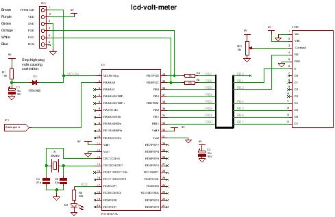
This PIC LCD volt meter project uses a PIC micro and an HD44870 LCD display. The analogue input is taken directly to the analogue input pin of the microcontroller without any other processing.
Specification
| Voltage range | 0V – 5V |
| Input signal level | TTL |
| Maximum input impedance | 2k5 |
The LCD volt meter uses the microcontroller power supplies as reference voltages and so it is not likely to be very accurate (e.g. a 7805 5V regulator has an accuracy of 4%).
 To improve accuracy add a voltage reference and feed the reference voltage to the Vref input on the PIC which is into RA3 ( change the control register values in the ADC to use the Vref). This project simply provides a quick and easy way of measuring volts without circuit complexity.
The project mainly shows how to control and setup the software to read an analogue value from the first analogue port RA0.
Note when designing using the analogue inputs its a good idea to start from AN0 as there is only a limited set of ways that more analogue ports can be selected for use (see the chip data sheet – analogue inputs).
| Compiler | Mikroelectronika MikroC Compiler Free! |
| Target | 16F877A (retargetable to other PICs that have Analogue input AN0). |
| Software level | Easy. |
| Software notes | Using fixed point long instead of floating point. |
| Hardware level | Easy. |
| Hardware notes | LCD will work with LVP (if PGM pin is pulled high). |
| Project version | 1.01 |
| Project files | Enter your details to get the Download Link and get the microcontroller newsletter: (Note: Your email is safe it will never be sold or rented). Note: Check your email for the project code download link. |
![Schematics and C code for a 0-5V PIC LCD Volt Meter.]() PIC lcd volt meter Hardware
PIC lcd volt meter Hardware
You can use any PIC microcontroller that has an ADC and enough memory to hold the program.
The LED is pulsed after every ADC acquisition to indicate that the processor is alive – so you can tell if the software is active.
You can program the PIC in circuit through the ICSP connector.
For more detail: Schematics and C code for a 0-5V PIC LCD Volt Meter.
The post Schematics and C code for a 0-5V PIC LCD Volt Meter. using pic microcontoller appeared first on PIC Microcontroller.
