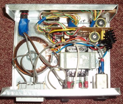
The power supply descriped here, is for turntables with 2 phase AC motor, like Linn, Rega, AR, Heybrook, Goldring and many, many more. The main features of the power supply are:
- X-tal controlled speed. The TTPSU can change speed by the push of a button – no need to move the belt on the pulley.
- Speed selection – 2 to 4 speeds can be configured and adjusted.
- Speed adjustment by varying the AC frequency in 0.1% steps.
- Approx. 15W output capability.
- DC free AC output. Also, spikes and noise on the net is eliminated.
- Optional lowering of the operating speed after start-up (110V->85V, 230>170V). High voltage output time can be set to 10, 25 seconds or always. A lower operating speed reduces the vibrations from the motor.
- Speed ramping to allow speed changes with the pickup in the groove with a minimum of vibrations and “soft” startup.
- 3 button control.
- 16×1 LCD display.
- Microprocessor controlled “Sinus” generation.
- Optional 50/60Hz input.
- Build for 110V or 230V input, 110V/230V output.
- Optional 50Hz/60Hz ouput (by downloading the appropriate program to the processor).
- Optional cleaner sinus for 60Hz operation (download) by overclocking the processor.
- It’s relatively cheap to build!
WARNING – IMPORTANT NOTE
This project is connected to 220V-240V mains supply alternatively the 110V-130V mains supply and is potentially lethal. Futhermore, it proceduces lethal output voltages (again 110V-130V/220V-240V). As a result of this, please observe the following:
- Do NOT build this project unless you are completely familiar with mains wiring practices.
- The circuit MUST be built into a fully enclosed case – if at all in doubt, please use an isolating plastic enclosure.
- Do NOT touch anything inside the case, when the curcuit when it is powered (even if turned off). The PCB does not carry any dangerous voltages, but it is all to easy to touch anything carrying lethal voltages (mains input, transformer connectors, fuse wires, mains switch connectors etc.).
Quick links
Input transformer/Power supply
Microprocessor controlled sinus generator, the DAC and filter
Gain stage and power amplifier
Mounting the construction in an enclosure
Possible improvements in a future v2 of the TTPSU
Tools used during development of TTPSU
Construction details
Here’s a run down of the idea behind the TTPSU and some reasons for selecting the individual components:
- PIC16F870 or PIC16F883 processor with resistor DAC for Sinus generation.
- Filtered sinus to make the sinus cleaner (less distortion).
- Class (A)B power amplifier.
- Stabilized power supply for the microcontroller and amplifier circuits.
- Transformer step-up for generating 110/230V output.
- Fuse protected output for overload protection.
The Microchip PIC16F870 was originally selected for several reasons. First of all, a Microchip processor was selected as I have both a selection of PIC’s and the development tools needed. The selection of 16F870 was based on the need for an external crystal for maximum speed stability and precision, the need 6 outputs for the DAC (port B<0:5>), 3 inputs for input control (port A<0:2>), 1 input/output for reduced operating voltage (port A<3>) and 6 outputs for display control (port C<0:1,3:5>). For a total of 16 I/O pins, the closest processor I had, was the 16F870. These days (2012/2013) the 16F870 has become more difficult (and expensive) to obtain, so I have added the option of using a 16F883 as well – just download the appropriate software for the selected processor.
The resistor DAC was selected for the following reasons: It’s cheap! It uses 7 standard 5% E12 resistor values (measure for optimal precision) or alternatively 7 1% E96 resistor values. I figured I could get a reasonable sinus precision compared to low-cost external DAC’s, and a 6 step DAC was what was needed, due to the idea behind the speed regulation. Permitting the use of 7 standard E12 resistors, makes it possible to build the TTPSU from components “in the drawer” and updating the DAC with 1% resistors, if the construction suits you needs.
The class B output power amplifier was selected for these reasons: It’s simple – a class (A)B output stage based on an op amp with only a few external components. This is the absolutely worst amplifier you can build for audio purposes, but it measures very well on sinus signals (which is what we use it for) and it’s cheap.
The stabilized power supply was added to the design to make sure, that net noise and net spikes was filtered out from the output. A input net filter was added for good measure.
The fuse protection in the output (essential!!!) was added, so if somebody got the “good” idea of plugging in an amplifier or vacuum cleaner :-), the TTPSU does not blow up in smoke. The fuse should be a slow fuse, as the TTPSU, although rated at 15W, is able to deliver in excess of 20W for short periods. Also, I recommend you use as small a fuse as you can get away with (i.e. the turntable starts up at every speed without blowing the fuse) – this will make the fuse blow, if the turntable is somehow obstructed and protect the motor.
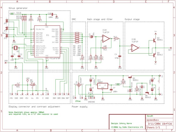
The concept behind the TTPSU is as follows: We take the mains input and transform it down to +/-15V and 5V for the microcontroller. The microcontroller and DAC (with filter) generates an approximate sinus signal, which is amplified and sent to the power amplifier. Finally, the output from the power amplifer is sent through the output transformer to generate the 120V/230V output. The microcontroller also handles the control buttons and the display.
The concept behind the TTPSU is as follows: We take the mains input and transform it down to +/-15V and 5V for the microcontroller. The microcontroller and DAC (with filter) generates an approximate sinus signal, which is amplified and sent to the power amplifier. Finally, the output from the power amplifer is sent through the output transformer to generate the 120V/230V output. The microcontroller also handles the control buttons and the display.
Detailed schematics
Input transformer/Power supply
The input transformer is 120V/230V primary and 2x15V secondary. The AC input is sent through a bridge rectifier and filtered with two 2200uF capacitors. A 7805 voltage regulator generates the 5V supply for the microprocessor, while the supply for the opamp and power amplifier is regulated with a transistor and zener diode for the positive and negative rail. Nothing fancy here  The construction uses BD911/BD912 transistors in the power supply, but these are not critical (just what I had at hand), so any power transistor which is able to dissipate 15W-20W should do, just make sure the pinout is the same.
Microprocessor controlled sinus generator, the DAC and filter
| The sinus generator is implemented as a Microchip PIC microcontroller and a simple resistor Digital to Analogue converter (DAC). The construction uses a simple 6 step resistor DAC to form a crude sinus, which is filtered to make an acceptable sinus. The filter has a -3dB frequency of 338Hz which was selected to allow for speeds exceeding 100 rpm for old records (e.g. 120 rpm will output a 181.82Hz sinus when using the 33 rpm pulley). However, for even better filtering, a frequency of 169Hz can be implemented, by replacing C4 with a 1uF capacitor in place of the default 470nF, which will still allow 78 rpm without any problems. | Note: The DAC can be implemented with two different resistor series – one using 5% resistors (easy to get, cheap) and one using 1% resistors. Both series has been tested, so that no combination of resistors within their stated tolerances causes a voltage reversal at any step in the DAC. | |
| Taking a look at the signal that comes from the DAC, we see the raw unfiltered output in figure 1. This output is from the prototype using 5% resistors. The big vertical steps comes from the use of an uneven resistor series, while the overshots in the picture is due to the “measurement equipment” (sound card used as oscilloscope for making the pictures). Another note about the pictures – the prototype was running a 12 MHz crystal (in place of a 20MHz) so the time scale is not correct! | ||
For more detail: TTPSU – Power supply for turntables with AC motors
The post TTPSU – Power supply for turntables with AC motors appeared first on PIC Microcontroller.


