Here is a simple tutorial on how to receive serial data from PC(Personal Computer) Hyperterminal and display it on 16×2 lcd using PIC16f877 microcontroller. Its not much difficult you just need to know how to use USART(Universal Syncronous-Asyncronous receiver transmitter) of PIC 16f877. Serial data is transmitted and recived by PC using DB-9 OR DB-25 port of PC.
Project Requirements
- PIC16f877 Microcontroller
- 16×2 lcd
- MAX232
- PC with DB-9 or DB-25 Port
- Potentiometer (For Setting LCD Contrast)
- Crystal 20MHz
- Connecting Wires & Power Supply
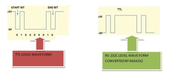
Microcontrollers works on TTL(Transistor Transistor Logic) wave form & Standard PC(Personal Computers) works on RS-232 level wave form. Serial Data Transmitted by PC is in RS-232c level wave form. We have to convert this RS-232c wave form data in TTL form, to pass it to PIC16f877. The best way is to use MAX-232 ic. MAX-232 converts RS-232c level wave form data in TTL & TTL data in RS-232c level. Below is a simple Diagram of both the wave forms.
Port-B of PIC 16f877 is connected to data pins of 16×2 lcd. RS(Register-Select) Pin of lcd is connected to Port-D Pin#6. En(Enable) Pin of lcd is connected to Port-D Pin#7. RW(Read-Write) Pin is grounded Because we only want to write to lcd. You can also connect RW pin to Port-D Pin#5 Because Rw is also programmed in software burned in PIC 16f877.
USART of PIC 16f877 is present at Pin 25 & 26 of PIC 16f877 Microcontroller. USART Include Port-C Pin#6 & 7. RC6 can be used as TX(Transmission) and RC7 can be used as RX(Reception). Since we are receiving data from PC and then displaying it on 16×2 lcd so we are only concerned with RX(Reception) pin of USART. This RX pin is connected to Pin#12(R1OUT) of MAX-232. Pin#13(R1IN) of MAX-232 is connected to PIN#3 of DB-9 Port.
Some Tutorials Regarding the project are.
Both the tutorials above are very important for you, if you are new and didn’t use the stuff before in any project. I recommend you to go through them it will help you a lot in understanding the circuit diagram and working of both the things. Circuit diagram of the project is given below.
Code is written in c language using MPLAB-ide and High Tech C compiler is used to compile the code. First High Tech C-compiler header file htc.h is imported in the project. Then Crystal frequency is defined which is 20MHz. RD7,RD6 & RD5 pins of Port-D are initialized as EN, RS & RW, Control pins for 16×2 lcd. lcdcmd() function is sending commands to lcd and control these commands. display() function is sending data to lcd, controls this data by controlling EN,RW & RS pins of lcd. lcdint() function is initializing our lcd and Microcontroller ports.
In the main function first TRISC7=1 is initializing RX pin as input. TXSTA(Transmit Status and Control Register) is initializing USART in Asyncronous Mode with High Speed Baud Rate. 0x04 is loaded in TXSTA.
Current Project / Post can also be found using:
- 16×2 lcd with serial port micro c
- how to program lcd 16×2 in pic 16f877a
- project pic16f870
- project using an lcd with pic16f877a
The post Serial Data Received from PC and Displayed on 16×2 Using USART of Pic16f877 Microcontroller appeared first on PIC Microcontroller.