Introduction
We designed a device that can aid in learning the alphabet in American Sign Language. We built a glove with various sensors to identify the hand position of the user closely and use that to give feedback on what they are doing right or wrong through the LCD display for each letter in the alphabet. The program detects how much the fingers are bent, contact between them, and hand orientation to determine this. The reason behind this project was to facilitate basic ASL learning for people that don’t necessarily need it, or may have someone in their lives with a hearing impairment. It means a lot when people that don’t have this difficulty learn or make an effort to learn ASL and facilitate communication, helping us to be more understanding and sensitive to those who don’t have the option of learning spoken languages.
High Level Design
The idea to do a project involving sign language began with an experience from one of the group members’ mom, who works as a social worker. She came across a college for the deaf, Gallaudet, which is partnering with Starbucks to open a signing only branch where all the baristas know sign language. People that don’t need sign language to communicate wouldn’t normally be inclined to learn it, so we thought it would be a good idea to design a device that can aid with learning sign language to increase accessiblility to those who speak it. The best way to learn is practice, so we decided to fashion a glove for our device and use various sensors to detect if the hand is in the correct position.
During the calibration state, the flex sensors measure the bend in 3 different position to set the thresholds for the states which are used to determine if each finger is bent enough for each corresponding letter. The first calibration step also sets the thresholds for the gyroscope and accelerometer to determine orientation and movement. The last component mounted on the glove are strips of copper tape used to detect contact, sending a high logical signal to the board indicating when 2 points make contact. The glove limits mobility a bit due to the large number of wire attached to it, which is a trade off for accuracy measuring accuracy. A cardboard box was also built to hold the components. The top level hold our board, with an opening to see the LCD display, while the bottom level contains the breadboard and the wires connected to the board. The top of the box also contains a button used to signal ready in the calibration stage, and a switch to go from learn mode to game mode and vice-versa.
Learn mode goes through the alphabet, and ensures the user holds the correct hand position for the corresponding letter for a second before moving to the next one, showing a picture of what it should look like and which parameter is not met, i.e. which finger is bent incorrectly, which axis to rotate the hand to get the right orientation, or wrong contact point. The game mode gives a time limit to get the correct hand position and keeps score of how many letters the user gets correctly, slowly decreasing the time limit.
Hardware Design
Our system takes includes a glove equipped with multiple sensors and a box housing our processor, display and buttons in order for the user to control the system. Below is an image of our final project.
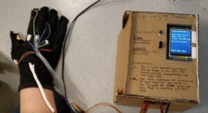
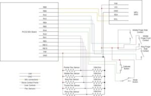
The glove contains 3 different types of sensors in order for the processor to differentiate between the different signs. First we have 5 flex sensors sewn into the glove for each of the 5 fingers. These flex sensors change resitance in accordance with how much they are bent. Each sensor is also pulled down by a 100kOhm resistor in order to achieve ideal values for the adcThis is useful in determining if the user’s fingers are in the correct position.
Next, we have an IMU, specifically the MPU 6050 which communicates with the processor through i2c. We placed this device in the center of the back of the hand. This device detects absolute orientation in space as well as acceleration in 3 different axis. We use the orientation (the output from the accelerometer), to determine if the hand is facing the correct direction. We use the motion data (output from the gyroscope) to determine if the motions for the letters requiring a movement (j and z) are correct.
The last type of input we take from the glove is from copper tape attached to certain contact points. One piece of the tape is powered while the other is connect to a pulled down GPIO pin. When the two pieces touch, the pin goes high, making the tape act as a switch. We use these inputs to determine if certain fingers are touching in the right location. Below is a diagram of where we placed each of the pieces of copper tape.
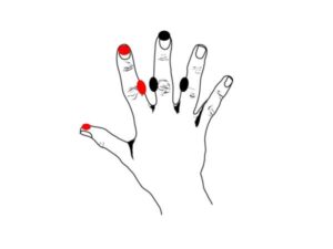
These inputs then feed into our box which includes all hardware wiring inside as well as our development board. The development board houses the pic32 processor and the tft display. On top of the box we have mounted a button and a switch. The button starts the callibration sequence and the switch changes between the learn and play modes. Both the button and the switch are attached to pins that have internal pull-down resistors enabled via the pic32. A full diagram of the schematic can be found here.
Software Design
i2c_helper.h
This file was originally created by Desmond Caulley (dc686 @cornell.edu), Nadav Nehoran (nn233@cornell.edu), and Sherry Zhao (hz263@cornell.edu) for use with their self-balancing robot project. You can read more about their project via the link in the references. This file provides several functions for communicating with the IMU, including a function that returns all the accelerometer and gyroscope readings in an array. For our project, we didn’t need nearly as much sensitivity as this function provided. Therefore, our version of the function ignores the lower bits in the accelerometer readings. Other than this, nothing major has been changed.
sign_language_learner.c
On startup, the main function sets up the five ADC inputs, TFT display, IMU, input pins, and threads. It also calls the init_signs() function to add the data on all 26 signs to the sign array. Then, it initializes and schedules the four threads.
Sensors Thread
The Sensors Thread, protothread_sensors, is responsible for polling the sensor values and saving them. This thread runs every 120ms to ensure that the user receives prompt feedback and that quick motions are detected. The thread polls the contact points, IMU data, and all five ADC inputs. In addition to saving the raw ADC values, the thread also handles debouncing of each finger’s bend level. By requiring several consistent readings before altering the recorded bend, the program lowers the effect of noise.
Calibrate Thread
The Calibration Thread, protothread_calibrate, is used to calibrate the accelerometer and bend levels for the specific user. It is run automatically at startup, and can be run again at any time by pressing the “calibrate” button. It has three stages; each describes a hand position for the user to make and prompts them to press “calibrate” when ready. Then 20 samples of the current sensor data are taken.
Each position corresponds to a level of bend in the user’s fingers. Every finger is calibrated independently of the others to account for differences in how easy or far they can be bent. The ADC values from each sensor are recorded and averaged over all the readings to define the boundary points between the different levels of bend. These boundaries are used to determine the positions of the fingers during the learn and game modes.
In addition, the first calibration position requires the user to place their hand flat on the table in front of them, with their fingers pointed straight ahead. This is used to calibrate the accelerometer readings from the IMU. Since the user could be facing any direction, it’s necessary to calibrate each time to make sure their hand is facing the correct direction relative to their body. Once calibration is complete, the thread yields until “calibrate” is pressed again.
Learn Thread
The Learn Thread, protothread_learn, is used to run the logic for “learn” mode. This thread only runs when the switch is in the lower position and calibration is complete. When run, the thread displays a letter, an image of the correct hand position, and a pair of indicators. Below is an example of what the tft displays during the learn mode.
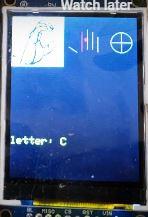
The first indicator is shaped like a hand; individual fingers turn red if they are incorrectly positioned, and white if they are correct. We chose to use the colors red and white because colorblind users would still be able distinguish them easily. Red dots on the fingers appear when a contact point at the indicated location is connected incorrectly. The second indicator, a circle with two lines through it, represents the hand’s orientation. If the x, y, or z orientation is incorrect, the corresponding line or circle turns red.
While a sign is being displayed, the thread checks the user’s hand position every 120ms. If the user is doing the sign correctly, a green circle will appear in the middle of the screen. An additional circle appears for every consecutive tick that the user is correct for; a mistake resets this. Once they reach five consistent readings, the sign is considered complete and the next letter in the alphabet is displayed.
To check if a sign is correct, the sign’s required bend levels are compared to the last recorded bend levels for each finger. The bend levels are defined as 0 (unbent), 1, and 2 (completely bent). Additionally, a finger position can be designated as “either 1 or 2”, which is useful for signs where the level of bend can vary while still appearing correct. Similarly, the contact point states and accelerometer values are compared to their ideal values. The accelerometer values have large deadbands (20 for x and y, 30 for z) to decrease the required level of accuracy while still rejecting signs that are blatantly wrong.
For signs that require a motion (j and z), more checks are hardcoded in. A single green circle will be displayed when the starting position is correct. After this, the gyroscope is used to detect a hand movement or rotation in the specified direction. For multi-stage motions, a timer gives the user 10 cycles to finish all movements, and an additional circle is added for each correct motion. Once the movement stops, the final orientation is checked; if it is correct, the sign is complete.
Game Thread
The Game Thread, protothread_game, is used to run the logic for “play” mode. This thread only runs when the switch is in the upper position and calibration is complete. The game thread works similarly to the learn thread, and uses the same functions to check if a sign is being formed correctly. However, there are a few differences.
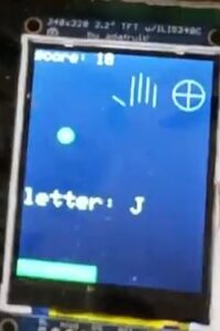
First, the letters are displayed in a random order instead of alphabetically, and the pictures are not shown. This increases the difficulty for the player. However, the error indicators are still visible to prevent the game from becoming too frustrating due to the level of precision required for some of the signs. Secondly, there is a time limit for each sign. If the timer bar (displayed at the bottom of the screen) runs out before the sign is completed, the words “GAME OVER” are displayed. Three seconds after a game over, a new game starts. The timer starts at a little less than 10 seconds, and gets steadily faster as the game continues. Finally, the number of signs the player has correctly completed is displayed in the upper left hand corner of the screen as their score. An example of the tft during the game mode is shown below.
Results
Our final product was able to detect the hand gesture with fairly close accuracy to the standard ASL letters.
In learning mode, our device was able to give accurate feedback in regards to corrections that needed to be made to signal the letter correctly. The images displayed for each letter were very clear, and allowed the user to get a good understanding of what his/her hand should look like. All 26 letters of the alphabet were tested and worked properly, and the display showed any changes or adjustments made by the user as soon as they were made. The game mode successfully displayed a green bar shrinking to signal time left, as well keeping score of the letters correctly signaled and slowly decreasing the time given to signal correctly.
The only safety concern we had was a potential fire hazard by having the wiring inside a cardboard box. To deal with this, we made sure we covered all the bare wire connections with electrical tape to avoid heat conduction, particularly the push button and switch as they come in direct contact with the cardboard. No interference with other designs needed to be accounted for.
All members of the group were able to use this device. This device is particularly designed for people with hearing impairment, so all instructions are either displayed on the screen or written in the box completely avoiding the use of sounds as intended. However, the glove is only one size so it’s not user friendly to people whose hand size isn’t compatible with the glove. Conveniently, all members of our group have similar sized hands and were all able to use it.
Conclusion
After spending a month working on our sign language learner, we are very happy with the results. We can reliably detect if a sign is being used correctly and feel that anyone who uses our product would be able to learn the ASL alphabet. The user interface is easy to understand and interactive. If given the change to continue working on this project, here are a few improvements we would consider:
- Improve checking of gyroscope values so the sign is recognized quicker.
- Add a “free play” mode in which the user could sign freely and the letters would appear on the screen.
- Include numbers and simple words or phrases to expand the systems capabilties.
- Redesign the glove so that the natural movements of the user are less hindered and the product is more refined.
All code in our main file was implemented by us, with a few components taken from previous labs, like the setting of the adc parameters. The i2c_helper.h file was created by a previous ECE 4760 group and has been cited as such with a link in the references. Our design is also not reverse engineered from another design, so there are no intellectual property concerns there.
We are all interested in publishing a piece about our design, as we are very proud of our final result. We will consider submitting a piece for publishing to IEEE.
We have followed all portions of the IEEE code of ethics. All components on the glove have been properly insulated and do not pose a threat to the user or the public. While working on the project, we followed all safety guidelines of the lab inlcuding wearing safety glasses while soldering. We were careful to not short the system and used all of the technicle knowledge we have gained in order to properly build the device. We accepted advice and critisism from the TAs and Bruce Land. The three of use all assisted each other in our professional growth while working on this project. We also do not face any legal issues with this product.
Although this system can be grown and iterated into something more refined, we met all of our individual goals while working on this project. We enjoyed our time working together and gained a lot of experience. We are pleased with the final system we have produced.
Schematic
Source: Sign Language Learner
The post Sign Language Learner appeared first on PIC Microcontroller.