Hi everybody
Ages and ages ago, I posted this and many people said they’d like a guide. So here it is!
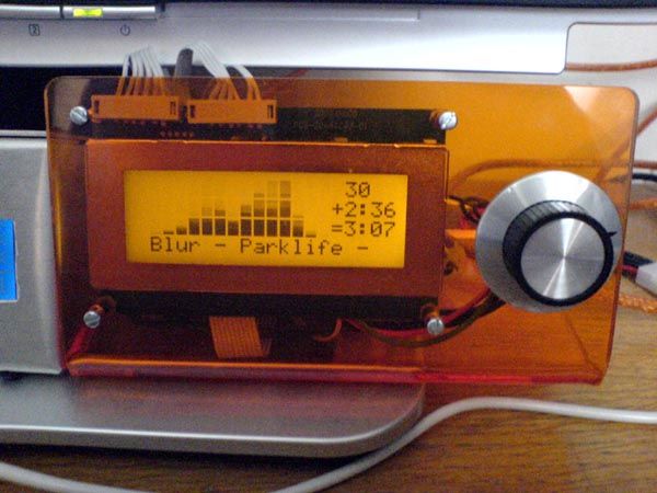
This is a guide for making an LCD that connects to your computer using USB, primarily intended to be external. You can see mine here. To make the board smaller, it doesn’t have the GPOs.

This thread should also be used for suggestions on how to improve the circuit, add new features, and fix bugs in the firmware.
Schematic and layout
First of all, the schematic.
The PCB layout in colour.
And a 300dpi printable version.
Component list:
R1; R8; R9; R10: 10k
R2; R7: 4k7
C1; C2: 22pF
C3; C5: 100nF
C4: 220nF
C6: 100uF
Q1; Q6: BC184L
RV2: 4k7 preset
LCD1: HD44780/KS0066U compatible
X1: 4MHz
T5: USB B (bought from Farnell)
J2: ALPS 11mm rotary encoder (from RS, part 263-2930)
BUZ1: miniature buzzer
U1: PIC18F2550 DIP28
Note that I’ve used a transistor for the buzzer, so you can connect someting else there instead… mod on!
The connection to the rotary encoder works like this: (diagram)
Pin 2 on encoder goes to pin 1 on J2
Pin 3 on encoder goes to pin 2 on J2
Pin 5 on encoder goes to pin 3 on J2
Pins 1 and 4 on encoder go to pin 4 on J2
Firmware
Here.
Installing in Windows
XP/2000: Download this to your desktop and tell Windows to use that as a driver when it asks.
Vista 64-bit: see scorpia’s post
I think Vista 32-bit works with the XP/2000 method, I’m not sure though.
This is the required programmer config (assuming 4MHz crystal). The USB voltage regulator is critical, as the PIC won’t even try to start up without it.
For more detail: Make your own USB LCD controller using PIC18F2550
The post Make your own USB LCD controller using PIC18F2550 appeared first on PIC Microcontroller.